
Mask device for photolithography and application thereof

a mask device and photolithography technology, applied in the field of photolithography mask devices, can solve the problems of difficult to achieve high etch selectivity of the underlying multi-layered film, difficult to utilize conventional lithographic techniques to manufacture features with dimensions less than 180 nanometers (nm), and difficult to pattern the repair buffer layer without damaging the underlying reflective multi-layered film. the effect of a single layer of reflection masks

Inactive Publication Date: 2005-11-10
UNITED MICROELECTRONICS CORP
View PDF4 Cites 4 Cited by
  • Summary
  • Abstract
  • Description
  • Claims
  • Application Information

AI Technical Summary

Benefits of technology

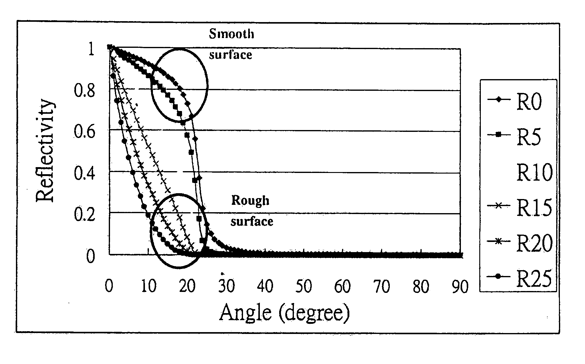
[0021] Next, an incident exposing radiation with an incident grazing angle is used to illuminate the surface of the single layer of reflection mask to result the partial portion of the incident exposing radiation is absorbed by the rough surface region, and other portion of incident exposing radiation is reflected by the smooth surface region. Thus, the rough surface region absorbed or scattered the incident exposing radiation, such that the pattern cannot transfer onto the wafer by incident exposing radiation. Thus, the rough surface region can define as zero, “0”. Otherwise, the smooth surface region reflected the incident exposing radiation, such that the pattern can transfer onto the wafer clearly by incident exposing radiation. Thus, the smooth surface region can define as “1”. The advantage of the present invention is that the pattern would be presented clearly onto the wafer.
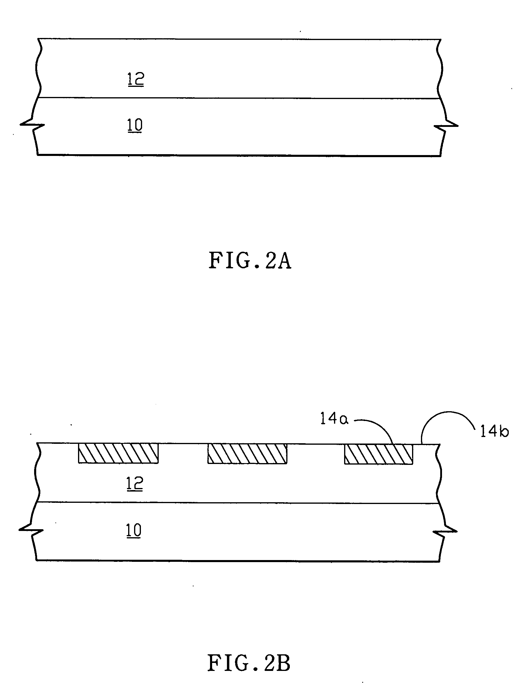
[0022] The structure of the photolithography mask is that a transparent substrate is provided, and a single layer of reflection mask with a defined pattern is on the transparent substrate. The single layer of reflection mask has a reflectivity as higher as the conventional multilayer of reflection mask, and the growth fabrication of the single layer of reflection mask is easier than the conventional multilayer of reflection mask. Furthermore, the defined pattern with a rough surface region is used to absorb or scatter the incident exposing radiation. Thus, the defined pattern onto wafer will present the dark area. The defined pattern further comprises a smooth surface region that is used to reflect the incident exposing radiation. Thus, the pattern onto the wafer will present the bright area.

Problems solved by technology

It is difficult to utilize conventional lithographic techniques to manufacture features with dimensions of less than 180 nanometers (nm).
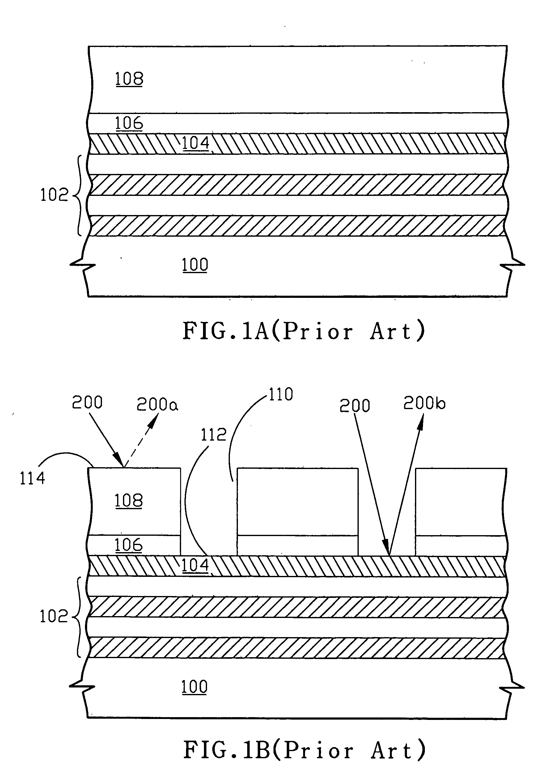
One problem with this two-layer process is the difficulty in patterning the repair buffer layer without damaging the underlying reflective multi-layered film.
The buffer layer can be patterned with a reactive ion etching technique, but a high etch selectivity to the underlying multi-layered film is difficult to achieve.
A wet etch to pattern the buffer layer can result in an undercutting of the buffer layer beneath the patterned absorber layer, and this undercutting produces other problems.
However, it is hard to grow or form a multiplayer masks with smooth and defect-free surfaces.

Method used


Image

  • Mask device for photolithography and application thereof
  • Mask device for photolithography and application thereof
  • Mask device for photolithography and application thereof

Examples


Embodiment Construction

[0027] Some sample embodiments of the invention will now be described in greater detail. Nevertheless, it should be recognized that the present invention can be practiced in a wide range of other embodiments besides those explicitly described, and the scope of the present invention is expressly not limited except as specified in the accompanying claims.

[0028] According to conventional photolithography process utilized normal incident exposing radiation to illuminate multilayer of reflection mask will cause the defect on the multilayer of the reflection mask. The growth of the conventional multilayer of reflection mask is very difficult when using the extreme ultraviolet exposing incident radiation. Thus, the present invention provides a structure and a method for forming a photolithography mask to simply the photolithography fabrication process, and the defect also can be reduced.

[0029] Referring to FIG. 2A to FIG. 2B, a transparent substrate 10 is provided, and a single layer of ...


PUM


Abstract

A mask device includes a single layer of reflection mask on a transparent substrate to simply the growth fabricating of the reflection mask, therefore, using single layer of reflection mask can easier control the defect. Furthermore, a pattern-transferring method for a photolithography process is to utilize the incident exposing radiation with a grazing incident angle to illuminate the photolithography mask, such that the pattern can be transferred onto the wafer clearly, and the resolution of the photolithography would be improved.

Description

BACKGROUND OF THE INVENTION [0001] 1. Field of the Invention [0002] The present invention generally relates to a photolithography mask device and the application thereof, and more particular to the photolithography mask device and the application thereof in which a photolithography mask device has a single layer of reflection mask with grazing angle incident exposing radiation. [0003] 2. Description of the Prior Art [0004] Semiconductor devices such as, for example, transistors in semiconductor components are manufactured using lithographic techniques. It is difficult to utilize conventional lithographic techniques to manufacture features with dimensions of less than 180 nanometers (nm). Accordingly, new lithographic techniques have been developed to more reliably manufacture sub-quartermicron features. As an example, Extreme Ultra-Violet Lithography (EUVL) can be used to manufacture features with dimensions of less than approximately 0.25 microns. [0005] EUVL uses extreme ultra-vio...

Claims


Application Information

Patent Timeline
IPC IPC(8): G03C5/00G03F1/14G03F9/00G21K1/06G21K5/00
CPCB82Y10/00G21K1/06G03F1/24B82Y40/00
Inventor LIN, BENJAMIN SZU-MIN
Owner UNITED MICROELECTRONICS CORP
Learn More