Compliant electrical contact assembly

a technology of electrical contacts and assemblies, applied in the field of very small compliant electrical contacts, can solve the problems of inability to make springs very small, inability to maintain consistent spring force from contact to contact, and relative cost of manufactur

Inactive Publication Date: 2005-11-10
ARDENT CONCEPTS INC
View PDF16 Cites 21 Cited by
  • Summary
  • Abstract
  • Description
  • Claims
  • Application Information

AI Technical Summary

Benefits of technology

[0017] Another object is to provide a low-self-inductance contact assembly that provides sufficient compliance to test various UUT's.
[0019] A further object is to provide a low-self-inductance contact assembly that is relatively inexpensive to manufacture.
[0023] The contact is placed within a through aperture in a dielectric panel. The aperture has openings at both ends of a center section. The contact can be captured within the aperture by a pin that extends through the center of the contact coil. Optionally, the remaining space of the aperture is filled with a compliant, electrically conductive elastomer that adds resiliency and aids in electrically shorting the coil loops.

Problems solved by technology

In addition, they are relatively expensive to manufacture.
Spring probes, however, have a size problem in that the spring itself cannot be made very small, otherwise consistent spring force from contact to contact cannot be maintained.
Thus, spring probes are relatively large, leading to an unacceptably large inductance when used for electrical signals at higher frequencies.
Additionally, spring probes are relatively costly since the three components must be manufactured separately and then assembled.
These contact solutions usually are less inductive than spring probes, but have less compliance and are capable of fewer duty cycles than spring probes.
However, these contacts still tend to be somewhat too large to be useful in some radio frequency (RF) applications.

Method used


Image

  • Compliant electrical contact assembly
  • Compliant electrical contact assembly
  • Compliant electrical contact assembly

Examples


Embodiment Construction

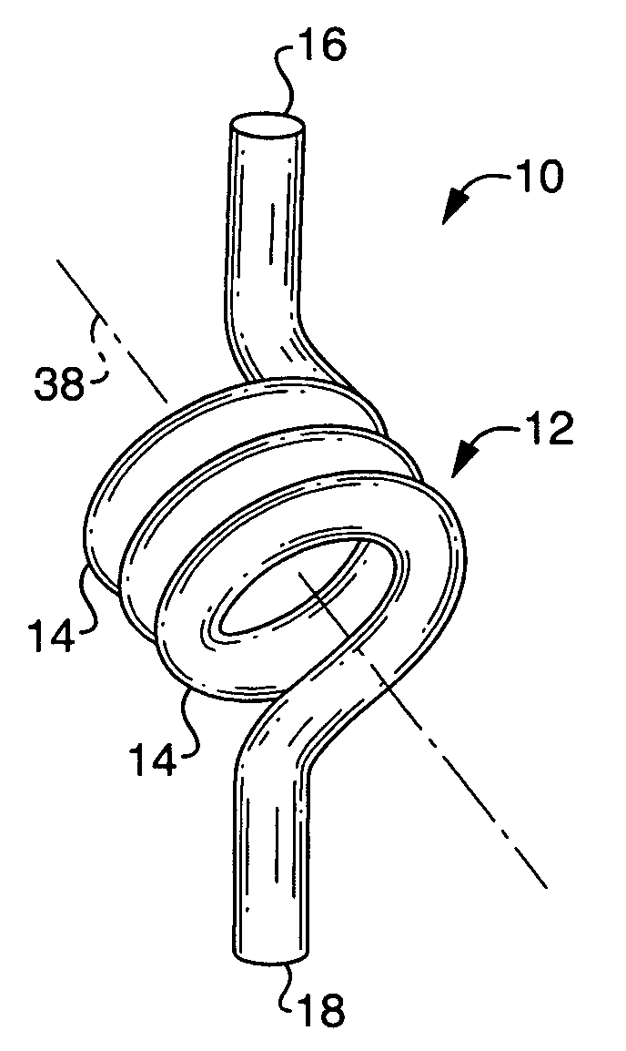
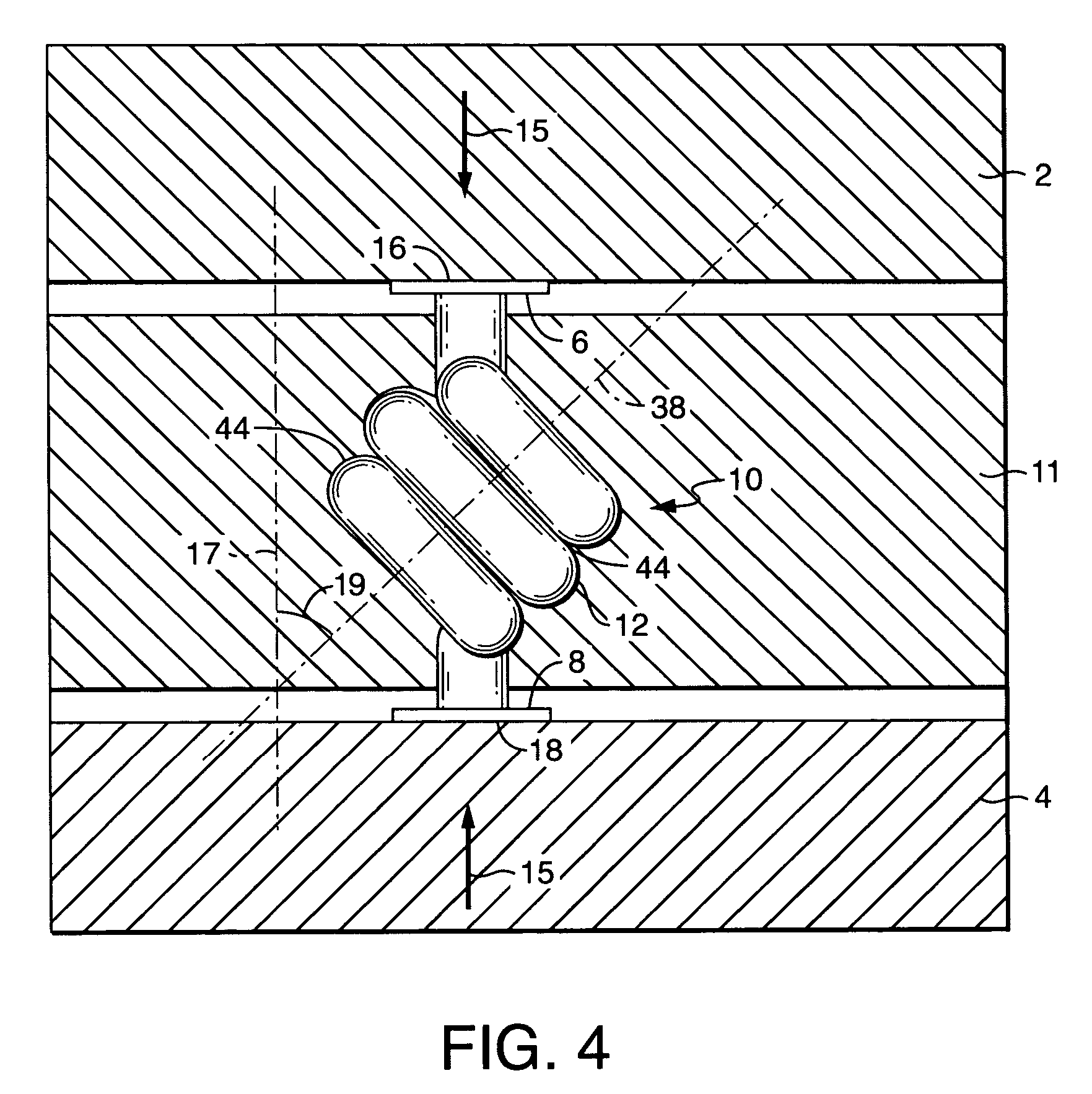
[0046] The present invention is an assembly 11 that provides an interface between two electrical devices, typically a unit under test (UUT) 2 and a test bed 4. The assembly 11 includes a compliant electrical contact 10 with a very low self-inductance.

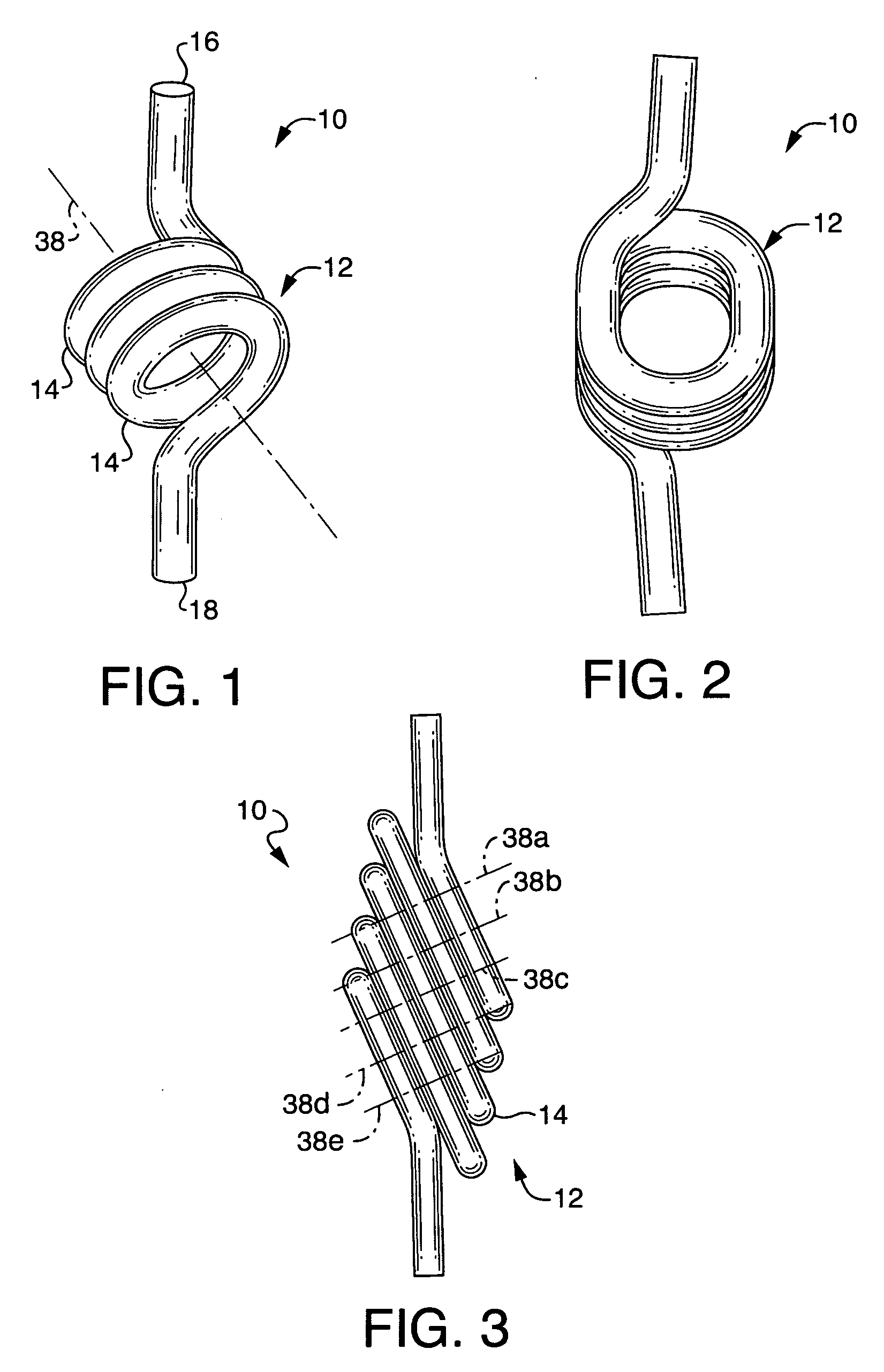
[0047] The contact 10 is created by winding or forming a length of electrically conductive material into a coil 12. The coil 12 can be round, as in FIG. 1, or oval, as in FIG. 2. The coil 12 can have a constant diameter or can have a diameter that changes, such a conical shape. The loops 14 of the coil 12 may have a single axis 38, as in FIG. 1, or each loop 14 may have its own axis 38a-38e, all of which are parallel, as in FIG. 3. The gap 44 between loops 14 of the coil 12, shown in FIG. 4, ranges from essentially no gap (a closed coil) to a distance of up to about 100% of the largest wire cross-sectional dimension. The greater the wire cross-sectional dimension, the greater the gap 44 can be as a percentage of the cross-sectional dim...


PUM


Abstract

A compliant electrical contact assembly for temporarily interfacing two electrical devices. The assembly includes a contact having loops with axes forming with a closed coil with opposed contact points. The axes is angled from the direction of the compression force holding the assembly sandwiched between the electrical devices. The electrically shorted loops of the coil slide on the surfaces of one another as the compression force is applied, providing compliance. The contact can be made extremely small such that pitches in the micrometer range can be achieved with very low inductance values. The contact is installed in a through aperture in a dielectric panel such that the contact points extend from opposed openings of the aperture. Optionally, the aperture is filled with a compliant, conductive elastomer.

Description

CROSS-REFERENCES TO RELATED APPLICATIONS [0001] The present application is a continuation-in-part application of application Ser. No. 10 / 834,727, dated Apr. 29, 2004 for COMPLIANT ELECTRICAL CONTACT ASSEMBLY in the name of Gordon A. Vinther, which is a continuation-in-part of application Ser. No. 10 / 341,723, dated Jan. 14, 2003 for COMPLIANT ELECTRICAL CONTACT in the name of Gordon A. Vinther, now U.S. Pat. No. 6,787,709, which claims the benefit of U.S. Provisional Patent Application No. 60 / 349,850, dated Jan. 17, 2002, for SKEWED COIL ELECTRICAL CONTACT, in the name of Gordon A. Vinther, and U.S. Provisional Patent Application No. 60 / 349,852, dated Jan. 17, 2002, for TANGLED WIRE ELECTRICAL CONTACT, in the name of Gordon A. Vinther.STATEMENT REGARDING FEDERALLY SPONSORED RESEARCH OR DEVELOPMENT [0002] Not Applicable REFERENCE TO A SEQUENCE LISTING, A TABLE, OR A COMPUTER PROGRAM LISTING COMPACT DISK APPENDIX [0003] Not Applicable BACKGROUND OF THE INVENTION [0004] 1. Field of the ...

Claims


Application Information

Patent Timeline
Patent Type & Authority Applications(United States)
IPC IPC(8): H01R12/00H01R13/24
CPCG01R1/06722G01R1/06733H01R9/096H01R2201/20H01R13/2421H01R13/33H01R12/714H01R12/52
Inventor VINTHER, GORDON A.
Owner ARDENT CONCEPTS INC
Why Eureka
Try Eureka