Check patentability & draft patents in minutes with Patsnap Eureka AI!

Sputtering device

a technology of sputtering device and substrate, which is applied in the direction of electrolysis components, vacuum evaporation coatings, coatings, etc., can solve the problems of increasing the cost of enlarge the target, and limiting the activity ratio, so as to reduce the cost and increase the yield rate of the substrate

Inactive Publication Date: 2005-11-17
CYG CORP
View PDF1 Cites 7 Cited by
  • Summary
  • Abstract
  • Description
  • Claims
  • Application Information

AI Technical Summary

Benefits of technology

[0006] The object of the invention is to provide a sputtering device which can design uniformity of film thickness distribution by corresponding to ablation change of a target and can gain a stable film quality by uniformity of film growth components.
[0010] Besides, the targets installed on the sputtering cathode units in the sputtering cathode devices consist of a same material. Accordingly, workability can be increased.
[0012] According to this invention, a cathode with a target is slanted to a rotating substrate and is moved along the substrate, so that a size of the target can be set no more than one of the substrate to achieve a decrease in costs, and a yield rate of the substrate can be increased because film thickness and film quality of the substrate is uniformed.

Problems solved by technology

Therefore, in JP 2003-247065 A discloses that the substrate table is moved up and down while rotated, but a mechanism for rotating and moving up / down the substrate table is complicated, as a result, disadvantage such that the costs are increased is arisen.
Accordingly, disadvantage for a film thickness distribution and a film growth is tried to be resolved by making a size of the cathode larger than the substrate (about 1.4 times) and by limiting activity ratio of the target, it becomes a cause of an increase in costs to enlarge the target and limitation of the activity ratio.

Method used


Image

  • Sputtering device
  • Sputtering device
  • Sputtering device

Examples


first embodiment

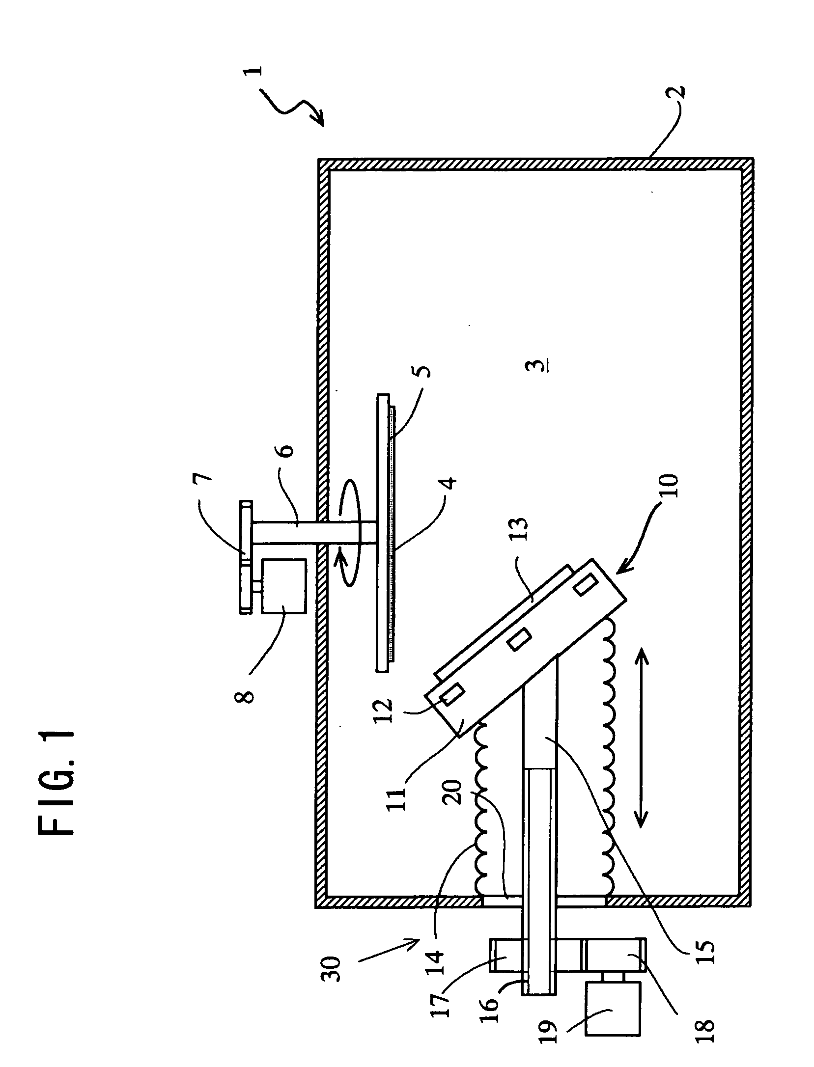
[0017] As shown in FIG. 1, a sputtering device 1 according to this invention comprises at least a vacuum container 2 defining a vacuum space 3, a substrate holder 5 holding a substrate 4 as a work in the vacuum container 2, and a sputtering cathode device 10 for sputtering to the substrate 4 held on the substrate holder 5. According to thus constitution, basically, gas for sputtering is introduced into the vacuum container 3 and a minus voltage is applied to a target 13 provided in the sputtering cathode device 10, so that sputter particles are radiated from the target 13 to the substrate 4 installed in the vacuum container 3 to form a thin film on the substrate 4.

[0018] Besides, the substrate holder 5 is rotated at a specific speed via a rotation shaft 6 and gears 7 by a electric motor 8 as a drive means. The rotational speed is variable by an outer control device not shown in figures and is set at a specific rate according to materials or thickness of the thin film formed on the s...

second embodiment

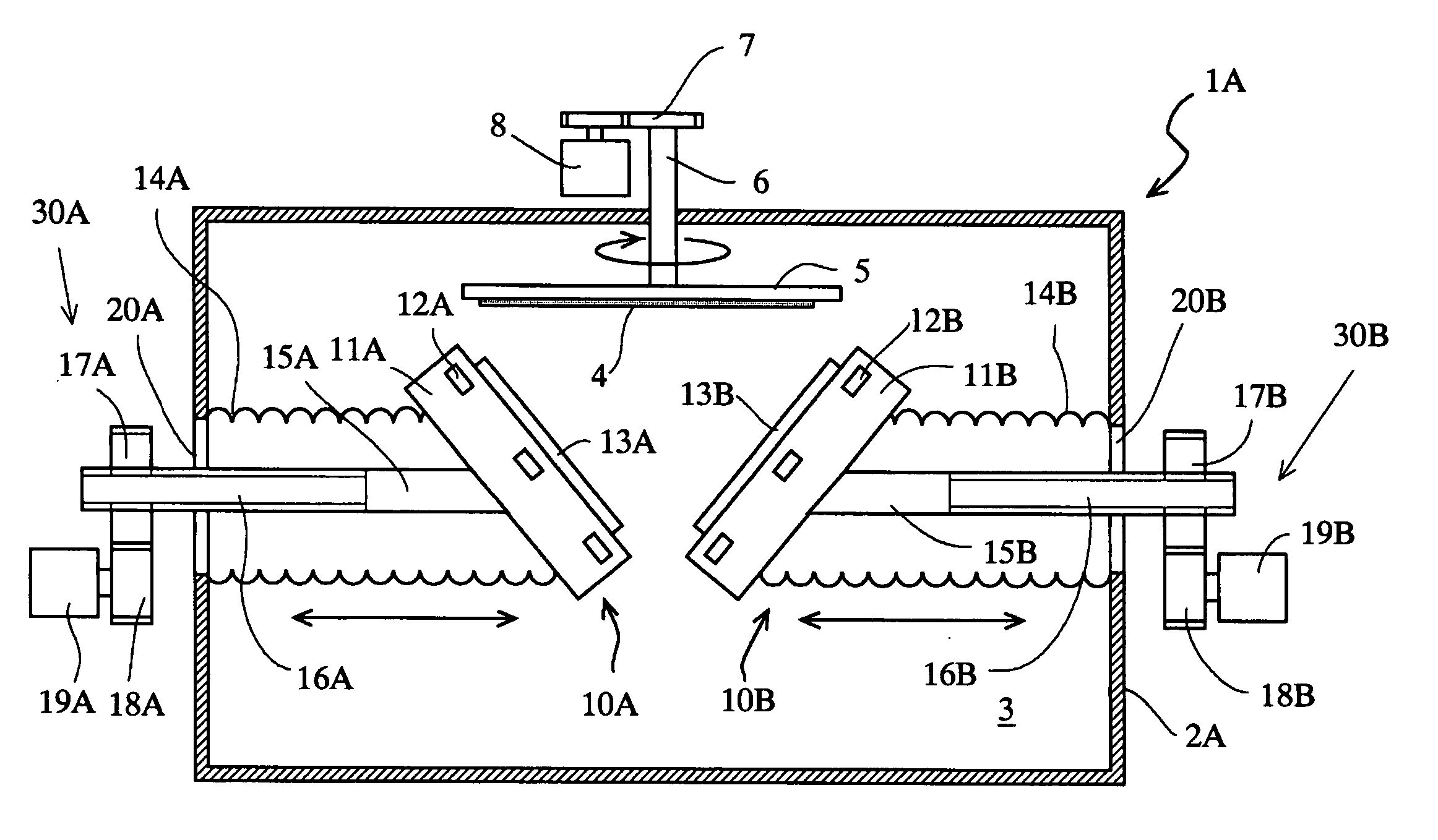
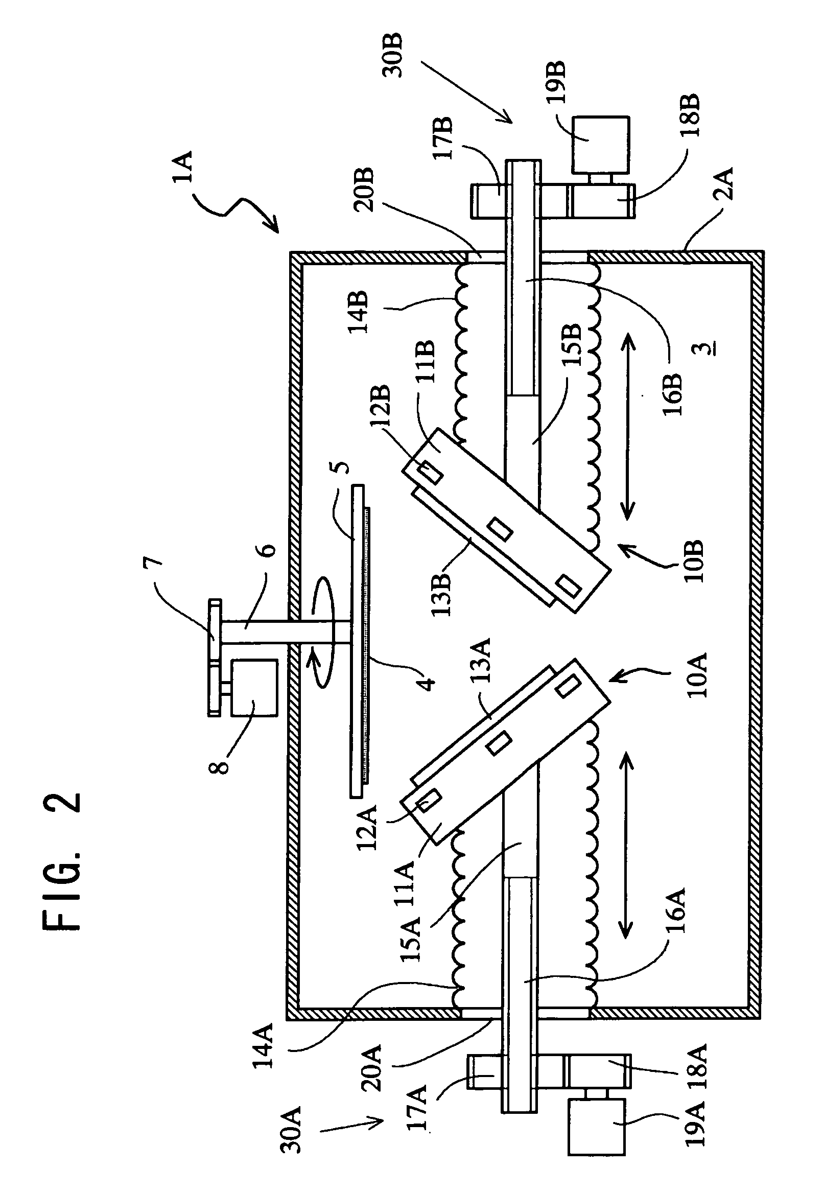
[0024] A sputtering device 1A according to the invention as shown in FIG. 2 is characterized in that plural sputtering cathodes 10A, 10B which are similar to or the same as the sputtering cathode device 10 are provided at specific intervals in a circumferential direction of the substrate 4.

[0025] The sputtering cathode device 10A, 10B are constituted of cathode unit 11A, 11B which are arranged slantly at a specific angle to the substrate 4, and movement unit 30A, 30B which make the cathode units 11A, 11B in parallel along the radial direction of the substrate 4, respectively.

[0026] The movement units 30A, 30B are, in the second embodiment, constituted of moving rods 15A, 15B which pass through openings 20A, 20B formed in the vacuum container 2, whose one ends are secured on the cathode units 11A, 11B and which have screw portions 16A, 16B formed spirally within specific areas at the other ends thereof, and driving gear 17A, 17B including inner teeth screwed on the screw portions 16...


PUM

PropertyMeasurementUnit
specific angleaaaaaaaaaa
specific speedaaaaaaaaaa
areaaaaaaaaaaa

Abstract

The object of the invention is to provide a sputtering device which can design uniformity of film thickness distribution by corresponding to ablation change of a target and can gain a stable film quality by uniformity of film growth components. Accordingly, a sputtering device according to this invention comprises at least: a vacuum container defining a vacuum space; a substrate holder for holding a substrate in said vacuum container; at least one sputtering cathode device which is provided with a cathode unit located at a position facing said substrate held on the substrate holder and arranged slantly at a specific angle to said substrate, and a means for moving cathode unit in parallel along said substrate; and a target installed on said cathode unit. The plural sputtering cathode devices can be also arranged at specific intervals in a circumferential direction of the substrate holder.

Description

BACKGROUND OF THE INVENTION [0001] This invention relates to a sputtering device comprising at least a vacuum container defining a vacuum space, a substrate holder holding a substrate in the vacuum container, a cathode located at a position facing to the substrate held on the substrate holder, and a target installed on the cathode. [0002] An ion beam sputter device disclosed in JP 2002-212724 A is provided with a vacuum container forming a space for processing a film formed object in the vacuum atmosphere, a plurality of ion sources for radiating ion beam to the vacuum container, a holder which is arranged within a movement area where every movement area of sputtering particles radiated from every target by radiation of the ion beam from every ion source are moved is overlapped and holds the film formed object, a shutter movably located in the vacuum container and preventing the sputtering particles from movement to the film formed object's side when it is positioned within a moveme...

Claims


Application Information

Patent Timeline
Patent Type & Authority Applications(United States)
IPC IPC(8): C23C14/34C23C14/32C23C14/35
CPCC23C14/3407C23C14/352C23C14/35
Inventor TAKAHASHI, NOBUYUKI
Owner CYG CORP
Features
  • R&D
  • Intellectual Property
  • Life Sciences
  • Materials
  • Tech Scout
  • Unparalleled Data Quality
  • Higher Quality Content
  • 60% Fewer Hallucinations
Learn More