Adaptive gate drive for switching devices of inverter

a technology of inverter and gate drive, which is applied in the direction of electronic switching, power conversion system, pulse technique, etc., can solve the problems of gate drive and other control circuit failure, parasitic oscillation within connected circuits, and difficult to maintain the voltage across the igbt within the safe operating area (rbsoa) of reverse bias

Active Publication Date: 2005-11-17
LETOURNEAU TECH DRILLING SYST
View PDF3 Cites 86 Cited by
  • Summary
  • Abstract
  • Description
  • Claims
  • Application Information

AI Technical Summary

Benefits of technology

[0008] A gate drive for an inverter adapts or modifies signals to a switching device, such as an Insulated Gate Bipolar Transistors (IGBT device) of an inverter, based on operating conditions of the inverter and IGBT device in order to control the turn-on and / or turn-off behavior of the IGBT device. The adaptive gate drive includes control circuitry having a Field Programmable Gate Array (FPGA) and includes power circuitry having a plurality of field-effect transistors (FETs). The control circuitry provides switching signals for operating the IGBT device. In addition, the control circuitry receives the operating conditions measured from the inverter. The operating conditions include an output current of the IGBT device, a temperature of the IGBT device, and a DC link voltage of the inverter.

Problems solved by technology

However, the very fast turn-off behavior of the trench gate IGBT device can make maintaining the voltage across the IGBT within the Reverse Bias Safe Operating Area (RBSOA) very difficult.
Additionally, the fast turnoff behavior of the trench gate IGBT device can cause parasitic oscillations within connected circuits.
Such parasitic oscillations can interfere with an / or cause failure of the gate drive and other control circuits.
Moreover, when a free wheel diode is used, as may be common in the inverter section of an AC motor controller, the very fast turn-on behavior of the trench gate IGBT can cause problems with the reverse recovery.
This can also cause parasitic oscillations and potential failure of the trench gate IGBT device and gate drive circuit.
Such problems are more significant at higher operating voltages and currents.
However, to effect control the turn-off behavior of the trench gate IGBT, the gate resistance has to be substantially increased by as much as 10 to 20 times. This substantial increase in resistance can create delays in the “turn off” of the trench gate IGBT device that may be generally unacceptable.
However, even though a gate drive is designed to survive such worst-case conditions, the power circuit rarely, if ever, experiences such worst case conditions.
Thus, the power circuit does not operate optimally when designed for the worst-case condition it will rarely, if ever, experience.
The slow switching behaviors result in increased heat dissipation along with resulting loss of equipment rating and / or reliability.

Method used


Image

  • Adaptive gate drive for switching devices of inverter
  • Adaptive gate drive for switching devices of inverter
  • Adaptive gate drive for switching devices of inverter

Examples


Embodiment Construction

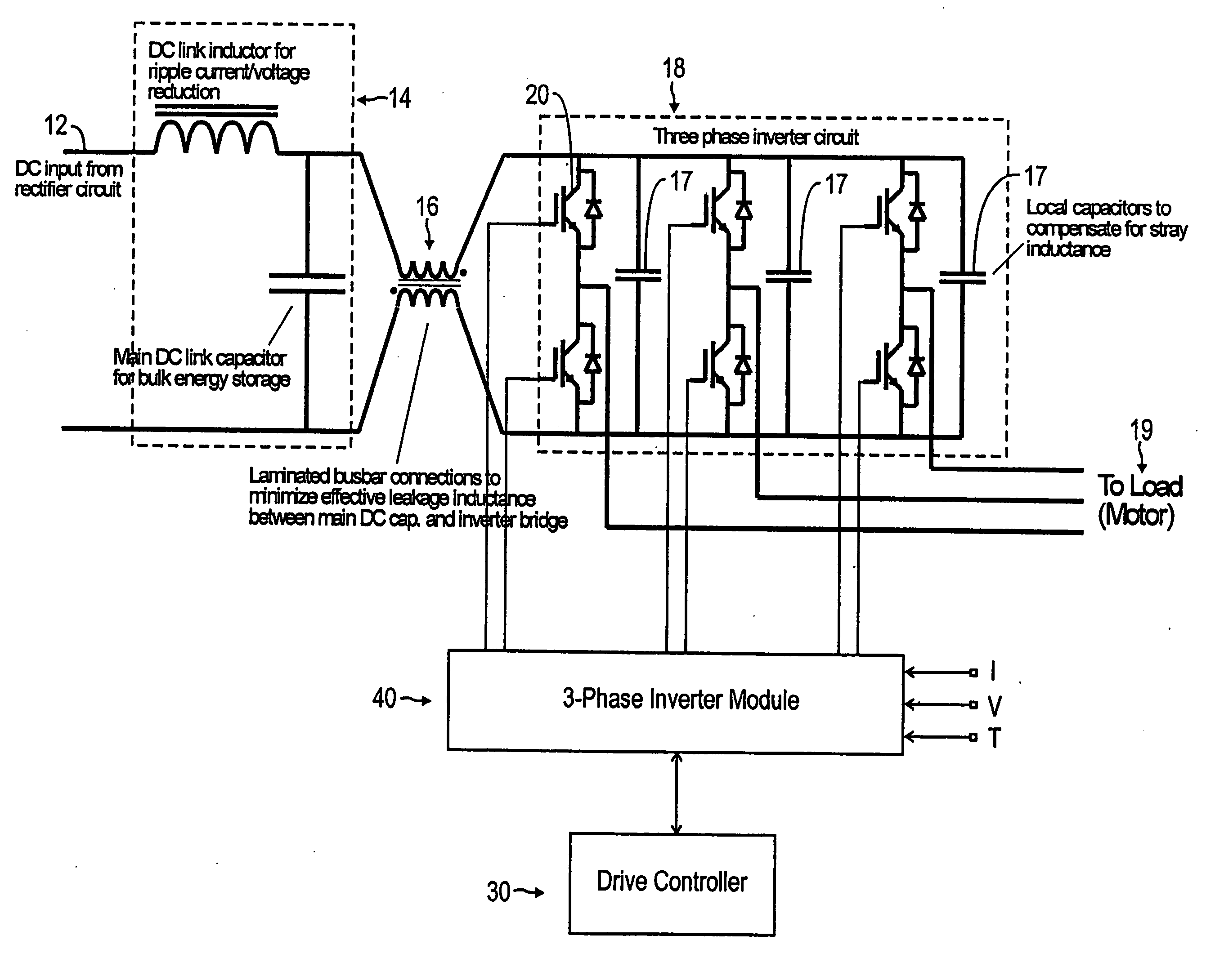
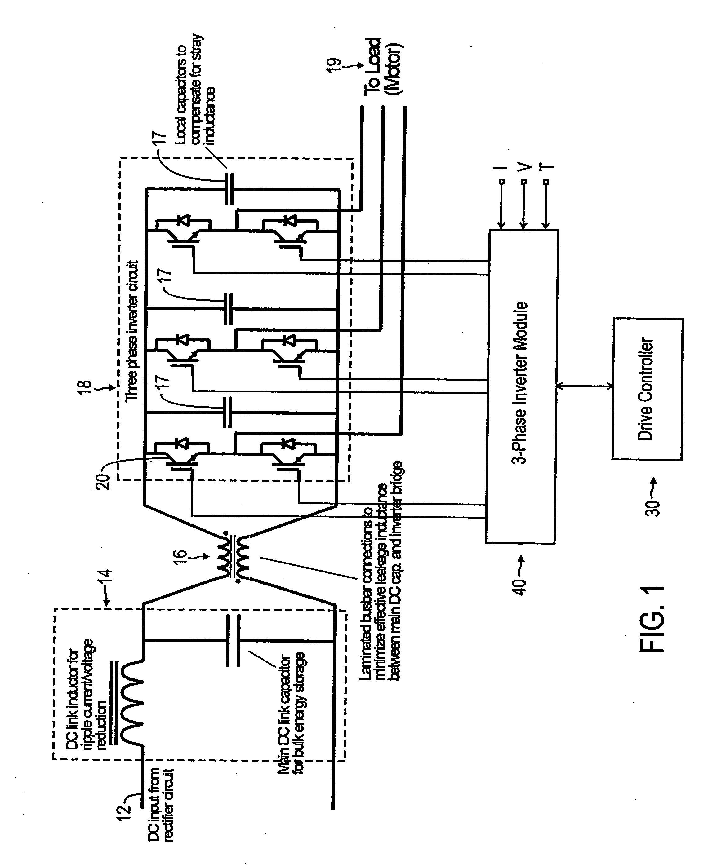
[0019] State-of-the-art, three-phase, alternating current (AC) motors use a sophisticated combination of solid state electronics, magnetic and / or vacuum contactors and other components configured into a control system. AC motor control systems may be distilled into four basic functional sections: (1) a input rectifier section that rectifies or converts incoming AC power into direct current (DC) power; (2) a DC bus section that may also filter and condition the DC power; (3) an inverter section that converts the DC power into a pulse width modulated (PWM), variable-frequency, AC signal; and (4) a control interface that allows a user to manipulate the control system and, therefore, the AC motor.

[0020] While the inventions disclosed herein were conceived in the context of using AC motors as prime movers in the oil industry, it will be appreciated that the inventions herein have much broader application than AC motors or a specific industry. Referring now to FIG. 1, portions of an AC m...


PUM


Abstract

An adaptive gate drive for an inverter includes control circuitry having a Field Programmable Gate Array (FPGA) and includes power circuitry having a plurality of FETs for operating a switching device, such as a Trench Gate Insulated Gate Bipolar Transistor (IGBT device). The control circuitry provides switching signals for operating the switching device. In addition, the control circuitry receives signals of output current of the IGBT device, temperature of the IGBT device, and DC link voltage. The FPGA has a plurality of operating points stored therein. Each operating point has corresponding parameters for a control signal that is used to control the turn-on or turn-off behavior of the IGBT device. During operation, the control circuitry compares the measured current, voltage and temperature operating points stored in the FPGA and sends the corresponding parameters to the gate drive circuit. The gate drive modifies the signal on the gate of the IGBT accordingly and thereby optimizes the turn-on and/or turn-off behavior of the device based on actual operating conditions.

Description

CROSS-REFERENCE TO RELATED APPLICATION [0001] This application is a non-provisional application of U.S. Provisional Patent Application Ser. No. 60 / 565,588, filed on Apr. 26, 2004, which is incorporated by reference.FIELD OF THE INVENTION [0002] This disclosure generally relates to an adaptive gate drive for semiconductor power devices and more particularly relates to an adaptive gate drive for an Insulated Gate Bipolar Transistor for controlling the turn-on and / or turn-off behavior. BACKGROUND OF THE INVENTION[0003] Semiconductor power switching devices, such as Insulated Gate Bipolar Transistors (IGBTs) or Metal-Oxide-Semiconductor Field-Effect-Transistor (MOSFETs) are well-known in the art. For example, IGBTs have been the main power semiconductors used in the inverter sections of variable speed AC motor drives and other similar applications. The latest generation of IGBTs includes Trench Gate Field Stop IGBT devices (TG-IGBTs), which are also sometimes referred to as third genera...

Claims


Application Information

Patent Timeline
Patent Type & Authority Applications(United States)
IPC IPC(8): H01L29/43H02M7/538H03K17/0414H03K17/082H03K17/16
CPCH02M7/538H02M7/5387H03K17/0414H03K17/0828H03K17/567H03K17/168H03K17/18H03K17/28H03K17/166
Inventor PACE, GARYROBBINS, LARRY CHARLES JR.
Owner LETOURNEAU TECH DRILLING SYST
Why Eureka
Try Eureka