Semiconductor device and method of manufacturing the same

a semiconductor and semiconductor technology, applied in the direction of semiconductor devices, semiconductor/solid-state device details, electrical apparatus, etc., can solve the problems of frequency dependence, drain breakdown voltage deterioration, kink in operation characteristics, etc., to improve reliability of semiconductor devices, and prevent overetching of semiconductor layers

Inactive Publication Date: 2005-11-17
RENESAS ELECTRONICS CORP
View PDF12 Cites 4 Cited by
  • Summary
  • Abstract
  • Description
  • Claims
  • Application Information

AI Technical Summary

Benefits of technology

[0027] Since the semiconductor device of the first aspect of the present invention comprises the silicon nitride film formed on a surface of an element with the first interlayer insulating film interposed therebetween, micro-defects which develop into lifetime killers are generated in the first semiconductor region which is the semiconductor layer below the isolation insulating film by a stress of the silicon nitride film and this shorten the lifetime of carriers (positive holes in an NMOS and electrons in a pMOS).
[0045] Another object of the present invention is to provide a semiconductor device of borderless contact structure which reduces the junction leak current to ensure downsizing and lower power consumption, and a method of manufacturing the same.

Problems solved by technology

Unlike a transistor formed directly on the semiconductor substrate, however, the semiconductor device of SOI structure in the background art has various problems caused by the floating-body effect since the semiconductor layer is electrically isolated from the semiconductor substrate by the buried oxide film.
For example, a kink in operation characteristics is caused and the drain breakdown voltage is deteriorated by carriers (positive hole in an NMOS and electrons in a pMOS) which are generated through impact ionization phenomenon in the active region and accumulated inside the semiconductor layer in a lower portion of a channel formation region, and frequency dependency of delay time is caused by instability of a potential in a channel region.
Even a semiconductor device having the isolation insulating film of PTI structure to fix the potential of the channel formation region, however, has a problem of causing the floating-body effect since the semiconductor layer below the PTI is thin (up to 50 nm).
When the semiconductor layer below the PTI is thin, the resistance between the wire and the transistor becomes higher as goes further away from the wire which fixes the potential of the channel formation region, to badly affect the characteristics of the transistor.
Further, there arises a variation in resistance of the channel formation regions in the transistors depending on the distance from the wire which fixes the potential of the channel formation region, which disadvantageously causes a variation in element characteristics.

Method used


Image

  • Semiconductor device and method of manufacturing the same
  • Semiconductor device and method of manufacturing the same
  • Semiconductor device and method of manufacturing the same

Examples


Embodiment Construction

The First Preferred Embodiment

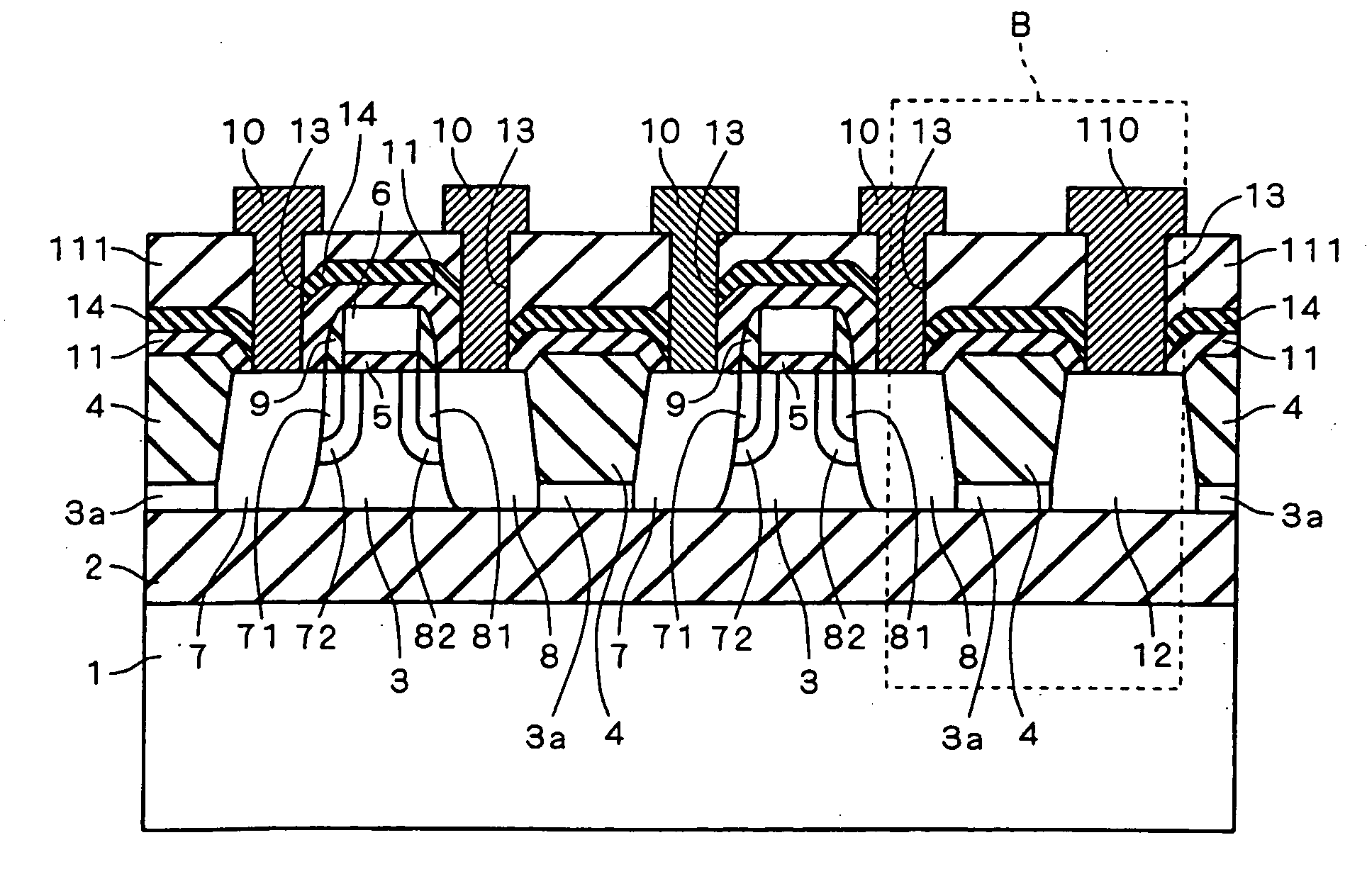
[0062]FIG. 1 is a cross section showing a semiconductor device in accordance with the first preferred embodiment of the present invention. The semiconductor device of FIG. 1 comprises a semiconductor substrate 1, a buried oxide film 2, a semiconductor layer 3, an isolation insulating film 4, a gate insulating film 5, a gate electrode 6, source / drain regions 7, 71, 8, and 81, pocket implantation regions 72 and 82, a sidewall insulating film 9, wires 10 and 110, interlayer insulating films 11 and 111, a p-type impurity region 12, a contact hole 13 and a silicon nitride film 14. Further, the semiconductor layer 3 (the first semiconductor region) below the isolation insulating film 4 is particularly represented as 3a.

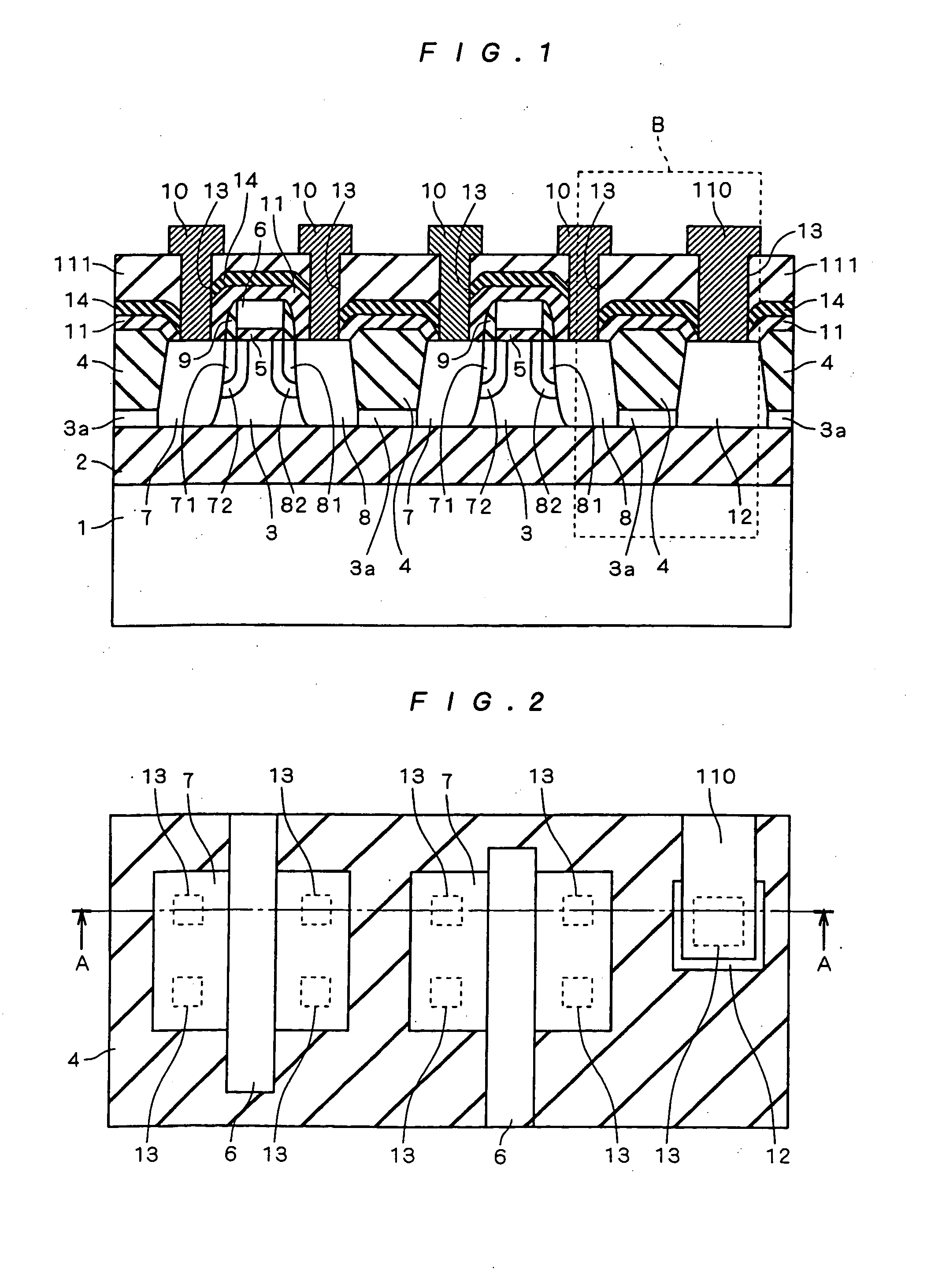
[0063]FIG. 2 is a plan view showing the semiconductor device in accordance with the first preferred embodiment of the present invention. FIG. 1 is the cross section taken along the section A-A of FIG. 2. In FIG. 2, the interlayer insulating f...


PUM


Abstract

A silicon nitride film is formed between interlayer insulating films covering an upper surface of an element formed on a surface of a semiconductor layer. With this structure, a semiconductor device comprising an isolation insulating film of PTI structure, which suppresses a floating-body effect and improves isolation performance and breakdown voltage, and a method of manufacturing the semiconductor device can be obtained.

Description

BACKGROUND OF THE INVENTION [0001] 1. Field of the Invention [0002] The present invention relates to a semiconductor device having an SOI (Silicon On Insulator) structure and a method of manufacturing the same, and more particularly to a semiconductor device having an isolation insulating film (hereinafter, referred to as a PTI (Partial Trench Isolation) which does not reach a buried oxide film and a method of manufacturing the same. [0003] 2. Description of the Background Art [0004] A semiconductor device having an SOI (Silicon On Insulator) structure consisting of a semiconductor substrate, a buried oxide film and a semiconductor layer has no possibility of causing a latch up even if a CMOS transistor is formed since an active region is surrounded by the buried oxide film and a device isolation (hereinafter, referred to as an FTI (Full Trench Isolation) which reach the buried oxide film). Further, the semiconductor device of SOI structure, in which a transistor is formed on the th...

Claims


Application Information

Patent Timeline
Patent Type & Authority Applications(United States)
IPC IPC(8): H01L21/314H01L21/318H01L21/76H01L21/762H01L21/768H01L21/8238H01L21/84H01L23/522H01L27/08H01L27/092H01L27/12H01L29/786
CPCH01L21/3143H01L21/3185H01L21/84H01L21/76283H01L21/76264H01L21/02126H01L21/02271H01L21/02129H01L21/0217H01L21/02164H01L21/02274H01L21/022H01L21/76
Inventor MATSUMOTO, TAKUJIIWAMATSU, TOSHIAKIHIRANO, YUUICHI
Owner RENESAS ELECTRONICS CORP
Why Eureka
Try Eureka