Vented mold and method for producing molded article

a technology of vented molds and molded articles, which is applied in the direction of manufacturing tools, food shaping, drawing profiling tools, etc., can solve the problems of defective molded articles, defective molded articles, and waste of liquid foamable polymeric compositions which move into the vents

Active Publication Date: 2005-11-17
PROPRIETECT LP
View PDF20 Cites 14 Cited by
  • Summary
  • Abstract
  • Description
  • Claims
  • Application Information

AI Technical Summary

Benefits of technology

[0026] The approach used by the present inventors is to de-emphasize location of a great number vents in potential areas of concern in the mold. Rather, the present inventors have discovered that the use of one or more grooves / slots in the mold cavity surface effectively acts as a siphon to draw gas away from the composition to be molded. The at least one groove and / or slot is connected to one or more vents which then allows for escape of the gas from the mold cavity to the exterior of the mold.
[0027] In a highly preferred embodiment, the one or more grooves / slots are provided in a so-called network or grid-like orientation to cover a substantial portion of the surface of the mold cavity as a web (e.g., a substantial portion of the surface of the mold cavity corresponding to the B-surface of the finished part). This allows for the use of significantly fewer vents and for de-emphasis on precise location of the vents in each potential area of concern in the mold cavity. Equally or more importantly, the provision of such a groove and / or slot, preferably in the network or grid-like fashion described herein, results in the significant advantage of production of molded articles that are free of the problem of foam collapse, voids and / or underfill.
[0029] It is possible to produce foam parts having relatively low density while obviating and / or mitigating the risk of occurrence of foam collapse. Previously, one approach to manage the risk was to design the chemistry of the foamable composition to result in a relatively high density product. The potential to produce relatively low density products using the venting approach described herein would result in lighter weight products—this would be highly advantageous in vehicular applications given the increasing cost of fuel.
[0031] It is possible to solve collectively the problems of foam collapse and the occurrence of underfill and voids in the foam product.
[0032] It is possible to significantly reduce the number of vents need to achieve adequate venting of the mold. This provides savings in capital costs and in maintenance. Further, the ability to use significantly fewer vents creates a predictable environment around the vents (and the mold). This creates the potential to manage the environment around the vents (and the mold) in a manner which obviates and / or mitigates uncontrolled release gas from the mold.
[0033] The one or more grooves / slots in the mold cavity surface are effectively self-cleaning in that, after gases are vented from the mold, the mold cavity is filled and the resulting product is demolded with a “negative” of the one or more grooves / slots (e.g., in the form of one or more ridges). There is little or no fouling of grooves / slots either by the moldable composition and / or by any mold release agents initially sprayed on the mold cavity surfaces to facilitate demolding. Avoiding fouling by mold release agents is particularly advantageous since such agents are regularly used in the art and would be expected to be applied to the one or more grooves / slots.

Problems solved by technology

Failure to adequately vent the mold results in defective molded articles exhibiting symptoms of improper foaming such as surface hardening (or foam densification) and / or void formation in the finished article due to trapped gas or air bubbles.
At the other extreme, excess venting of the mold will also result in defective molded articles due to collapse of the foam prior to curing; this phenomenon is often referred to as the ‘soufflé’ effect.
During molding operations some liquid foamable polymeric composition which moves into the vent is wasted.
Further, as will be developed below, notwithstanding advances in the art pertaining to venting, there is still a problem with molded articles, particularly those made of polyurethane foam.

Method used


Image

  • Vented mold and method for producing molded article
  • Vented mold and method for producing molded article
  • Vented mold and method for producing molded article

Examples


Embodiment Construction

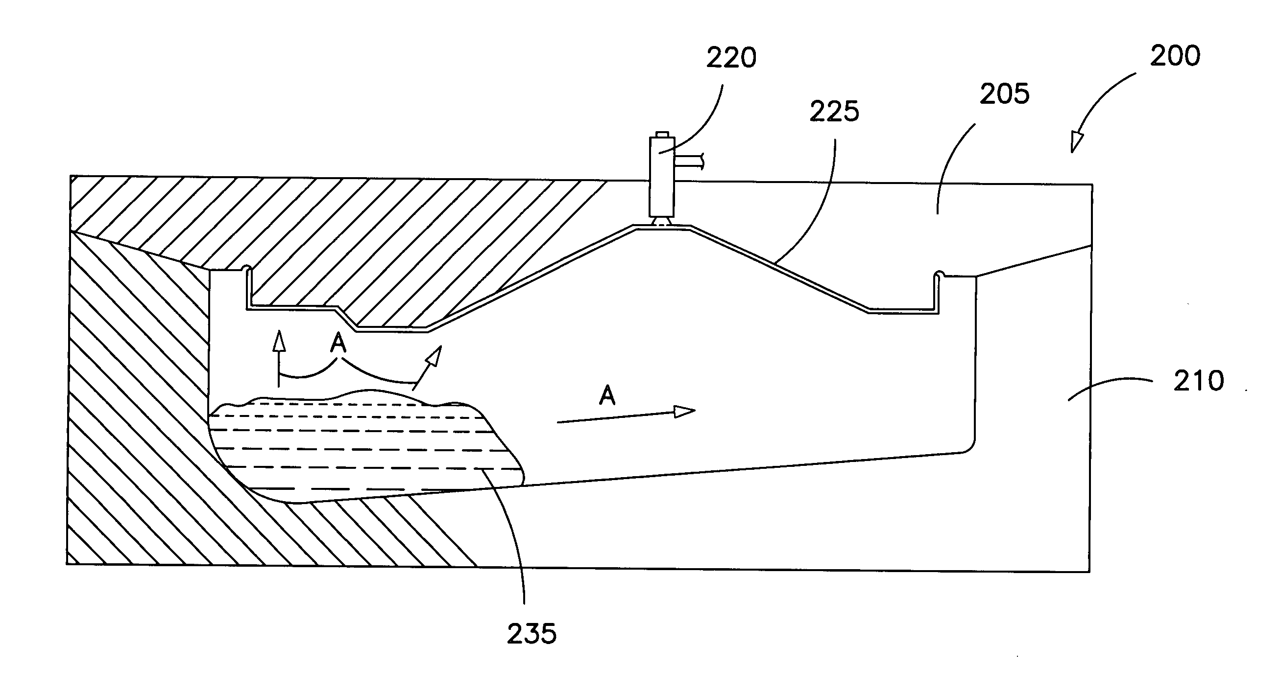
[0064] The most preferred liquid foamable polymeric composition is based upon polyurethane, which will be referred throughout this specification. However, it will be apparent to those of skill in the art that the present invention is applicable to other types of molding operations including, but not limited to, latex foam, neoprene foam, PVC foams and the like.

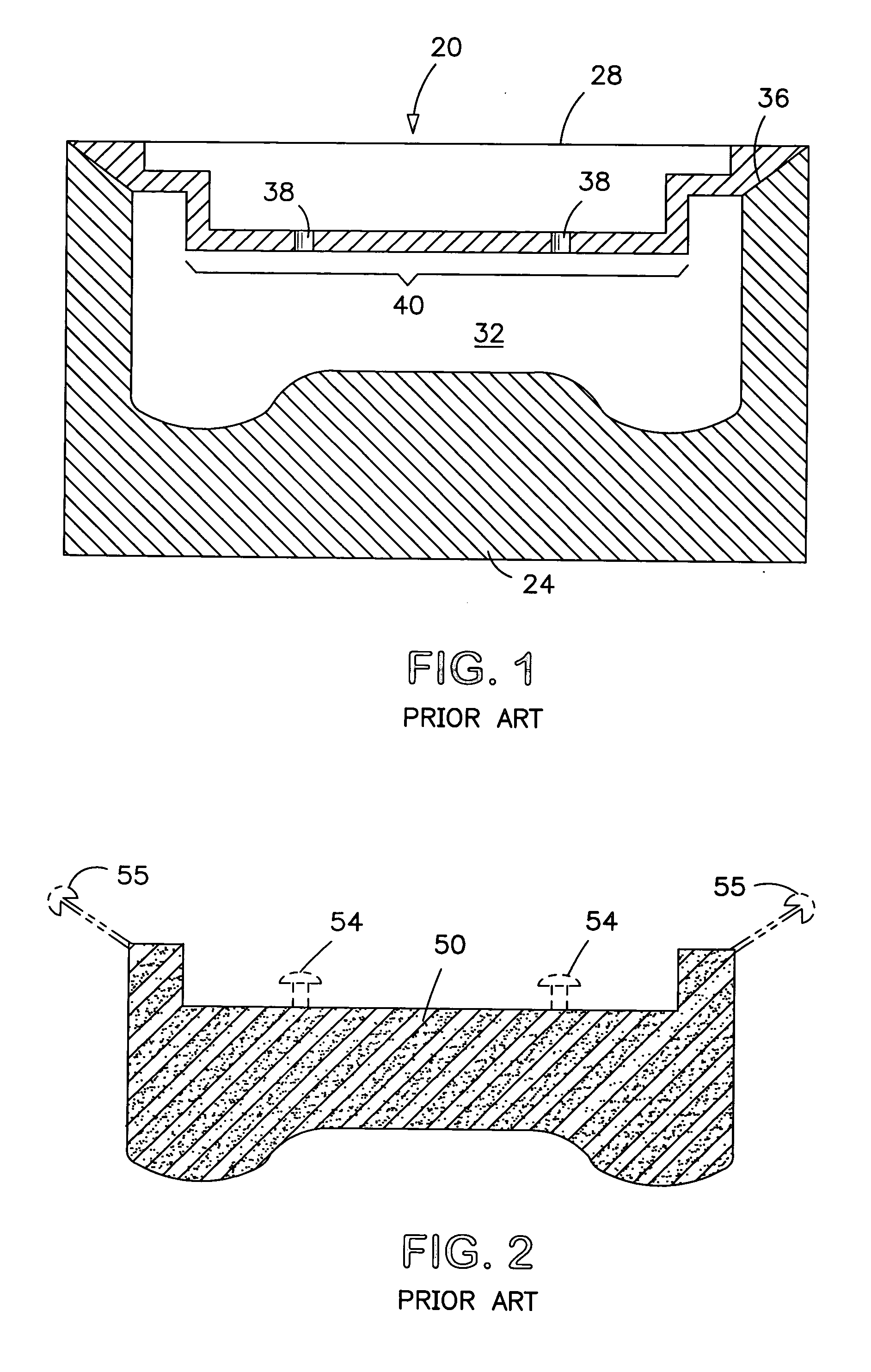
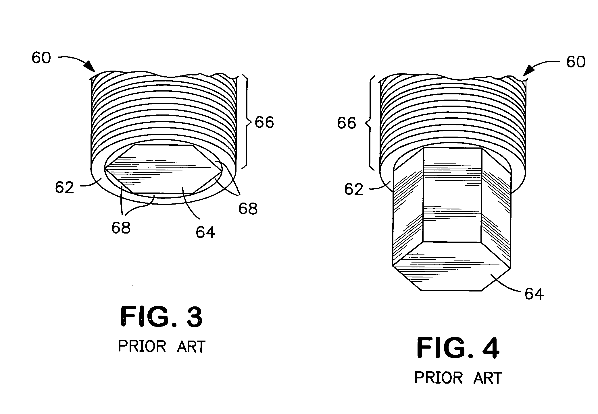
[0065] A first generation prior art mold will first be discussed, with reference to FIGS. 1 and 2, and a second generation prior art mold will then be discussed, with reference to FIGS. 3 and 4.

[0066] With reference to FIGS. 1 and 2, a typical clam-shell mold, similar to those used for forming an automotive seat cushion from polyurethane foam, is indicated generally at 20 in FIG. 1. Mold 20 includes a lower mold 24 (also known in the art as a “bowl”) and an upper mold 28 (also known in the art as a “lid”) which are joined by a conventional hinge or other means (not shown). Lower mold 24 and upper mold 28, when closed, define...


PUM

PropertyMeasurementUnit
widthaaaaaaaaaa
widthaaaaaaaaaa
widthaaaaaaaaaa

Abstract

The invention relates mold, particularly a mold for producing foam articles. In a preferred embodiment, the mold comprises a lid and a bowl releasingly engageable to define a mold cavity, the lid comprising: (i) a vent having a passageway for gas to escape from the mold cavity, and (ii) a plurality of grooves connected to the vent. The use of a plurality of grooves / slots in the mold cavity surface effectively acts as a siphon to draw gas away from the composition to be molded. The plurality of grooves / slots is connected to one or more vents which then allows for escape of the gas from the mold cavity to the exterior of the mold.

Description

CROSS-REFERENCE TO RELATED APPLICATION [0001] The present application claims the benefit under 35 U.S.C. §119(e) of provisional patent application Ser. No. 60 / 570,075, filed May 12, 2004, the contents of which are hereby incorporated by reference.BACKGROUND OF THE INVENTION [0002] 1. Field of the Invention [0003] The present invention relates to a vented mold and to a method for producing a molded article. [0004] 2. Description of the Prior Art [0005] Many articles are manufactured by placing a raw material into a cavity in a mold wherein the raw material undergoes a physical change (e.g., it expands or foams) and the article produced thus acquires the shape of the cavity. In particular, this technique is commonly employed for producing foamed articles made from polymeric foams such as polyurethane foam, latex (e.g., natural and styrene-butadiene rubber) foam and the like. [0006] For example, automotive seats are commonly manufactured from polyurethane cushions which are molded to s...

Claims


Application Information

Patent Timeline
Patent Type & Authority Applications(United States)
IPC IPC(8): B29C33/10B29C44/00B29C44/34B29C44/58B60N2/90
CPCB29C33/10B29C44/588Y10S297/01B29C44/5609B29K2075/00Y10S425/812B29C44/34
Inventor CATHCART, ALLAN K.CLARK, LESLIE E.GENYN, LARRY A.MENESES, LOUIE J.LANSUE, RANDALL J.
Owner PROPRIETECT LP
Why Eureka
Try Eureka