Bearing structure of crankshaft in internal combustion engine

a technology of internal combustion engine and bearing structure, which is applied in the direction of mechanical equipment, machines/engines, rigid support of bearing units, etc., can solve the problems of unavoidable play between the outer race of the left-side rolling bearing and the bearing hole of the crankcase, and the inability to obtain the desired bearing function,

Inactive Publication Date: 2005-04-14
HONDA MOTOR CO LTD
View PDF6 Cites 19 Cited by
  • Summary
  • Abstract
  • Description
  • Claims
  • Application Information

AI Technical Summary

Benefits of technology

[0012] The invention has been made in view of such circumstances and it is an object of the invention to provide a novel bearing structure of a crankshaft in an internal combustion engine whi

Problems solved by technology

However, when the pair of left and right rolling bearings are press-fit into both of the crankshaft and the crankcase as mentioned above, there arises a drawback that the assembling of the crankshaft to the crankcase and the maintenance after the assembling become difficult.
However, in such an operation, a phenomenon that some play is generated in the radial direction between the outer race of the left-side rolling bearing and the bearing hole of the crankcase is unavoidable.
Accordingly, at the time of running the internal combustion engine, there arises a drawback that a desired bearing function cannot be obtained besides the occurrence of a hitting sound attributed to the above-mentioned play.
Accordingly, the absorption of the play by the push plug becomes insufficient and hence, with respect to a high-output internal combustion eng

Method used


Image

  • Bearing structure of crankshaft in internal combustion engine
  • Bearing structure of crankshaft in internal combustion engine
  • Bearing structure of crankshaft in internal combustion engine

Examples


Embodiment Construction

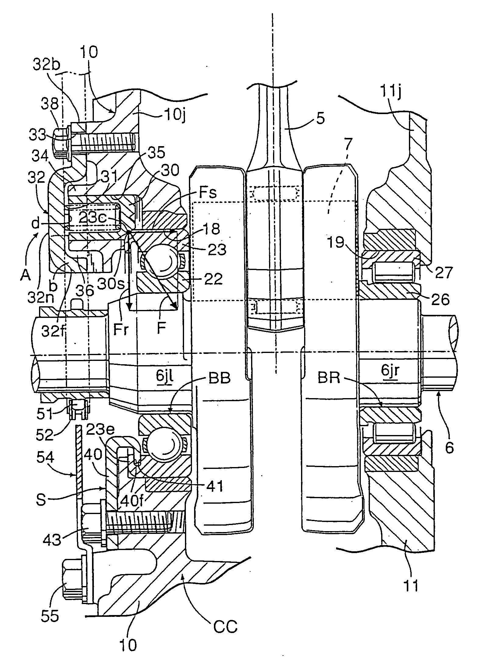
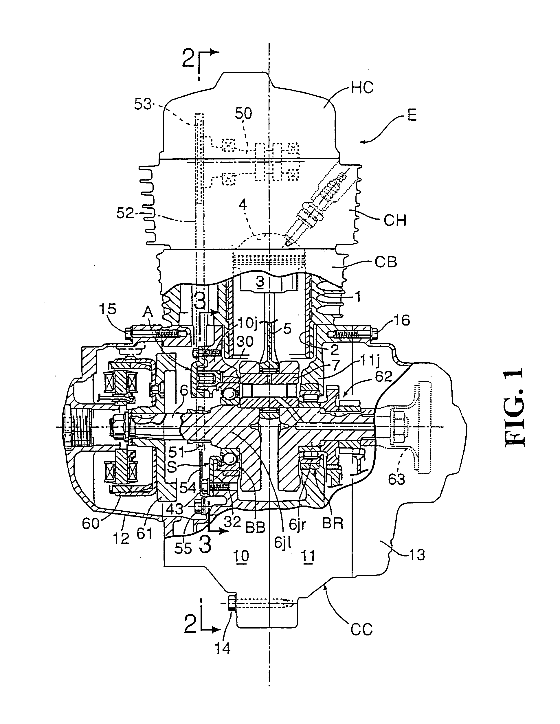
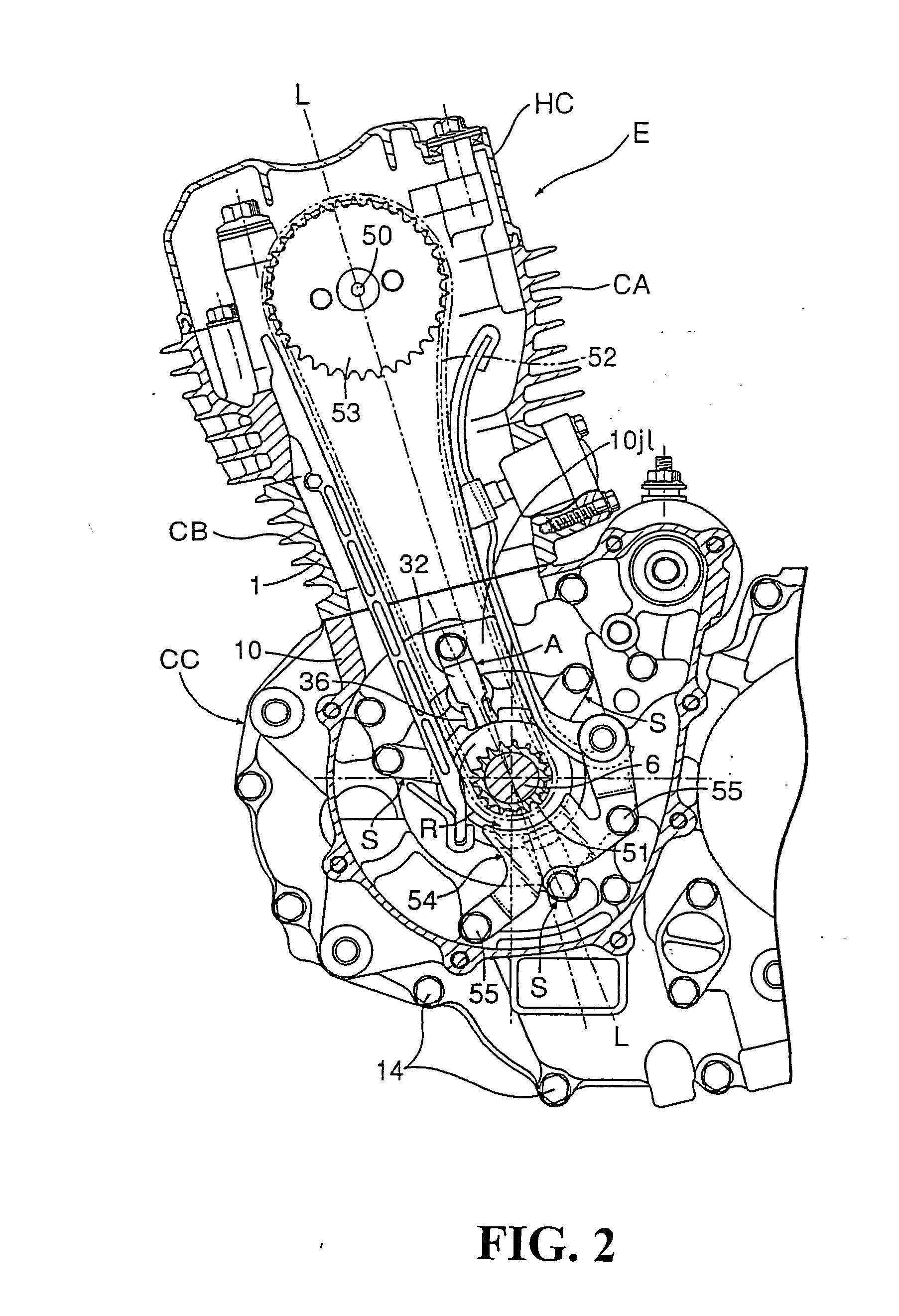
[0035] First of all, in FIG. 1 and FIG. 2, an OHC type 4-cycle single-cylinder internal combustion engine E includes a cylinder block CB, a cylinder head CH which is fixed to a deck surface of the cylinder block CB, a two (left and right)-split crankcase CC which is fixed to a lower portion of the cylinder head CH, and a head cover HC which is mounted on an upper surface of the cylinder head CH so as to cover the cylinder head CH. In a cylinder 1 having a cylinder sleeve 2 which is formed at a center portion of the cylinder block CB, a piston 3 is slidably fit. A combustion chamber 4 is formed in the cylinder head CH such that the combustion chamber 4 faces a top surface of the piston 3. A small end portion of a connecting rod 5 is rotatably connected to a piston pin of the piston 3, while a large end portion of the connecting rod 5 is rotatably connected to a crankpin 7 of the crankshaft 6. The crankshaft 6 is rotatably supported on the crankcase CC by way of left and right rolling...


PUM


Abstract

A bearing structure of a crankshaft in an internal combustion engine supports a crankshaft on a crankcase with rolling bearings includes a play absorbing device for absorbing the play in the radial direction generated between an outer race of the rolling bearing and a bearing hole of the crankcase. The play absorbing device includes a push plug which pushes an outer race of the ball bearing in the direction perpendicular to an axis of the crankshaft. The push plug is arranged in parallel to the crankshaft between the cylinder and the crankshaft. The outer race of the ball bearing is resiliently biased toward a side of the bearing hole of the crankcase which receives an explosion pressure. As a result, the generation of a hitting sound which is attributed to the above-mentioned “play” can be largely reduced even with respect to an internal combustion engine with a high explosion pressure.

Description

CROSS-REFERENCE TO RELATED APPLICATION [0001] The present application claims is related to Japanese Patent Application Nos. 2003-339418 and 2003-339416, both filed Sep. 30, 2003, the entire contents of which are hereby incorporated by reference. BACKGROUND OF THE INVENTION [0002] 1. Field of the Invention [0003] The present invention relates to the structure of a bearing which rotatably supports a crankshaft in a crankcase. [0004] 2. Description of Background Art [0005] In general, with respect to a single-cylinder internal combustion engine of a motorcycle or the like, a crankshaft is rotatably and pivotally supported in a bearing hole of a crankcase by way of a pair of rolling bearings, a piston which is slidably fit in a cylinder bore is connected to a crankpin of the crankshaft by way of a connecting rod, and an explosion pressure applied to the piston is received by the crankcase by way of the pair of rolling bearings from the crankshaft. In this case, it is desirable to ensure...

Claims


Application Information

Patent Timeline
IPC IPC(8): F02B67/06F02F7/00F16C9/02F16C25/08
CPCF02F7/0053F16C25/08F16C9/02F02B67/06
Inventor KANBE, TAKASHIYOKOYAMA, HIDEMIOBA, YUTAKAHASHI, AKIRAKIHARA, TERUO
Owner HONDA MOTOR CO LTD
Why Eureka
Try Eureka