System for forming stacks of composite materials

a composite material and stack technology, applied in the direction of lamination, lamination auxiliary operations, lamination, etc., can solve the problems of inability to manufacture more complex geometries, increase the structure of such systems, and jeopardize the quality of the part obtained, so as to reduce the number of creases, and improve the adaptability

Inactive Publication Date: 2014-10-02
APPLUS SERVICIOS TECHCOS
View PDF2 Cites 18 Cited by
  • Summary
  • Abstract
  • Description
  • Claims
  • Application Information

AI Technical Summary

Benefits of technology

[0018]Due to the flexibility of the rolling hollow forming cover, the pressure of the tread on the stack of composite material arranged on the mandrel element makes the sheets of the stack of composite material adapt to the contour of the mandrel element, such that as the pressure rolling forming device rolls in the longitudinal direction on the stack of composite material, successive parts of the stack are trapped between the smooth surface of the tread and the mandrel element. Therefore, the stack of composite material is compacted and formed with the desired end geometry with the passage through the pressure rolling forming device. The nature of the rolling hollow forming cover allows the cover to adapt to surfaces of stacks of composite material arranged on mandrel elements with shapes that have no side symmetry, so it allows forming stacks formed with sides having different configurations, which is a substantial advantage of the present invention compared with technology with solid, more or less rigid rollers used in conventional roll-forming systems.
[0019]On the other hand the rolling hollow forming cover has a greater capacity for adaptation than conventional roller systems do, absorbing to a greater extent the changes in the geometry of the mandrel element (for example joggles or asymmetries), and exerting the pressure more progressively, uniformly and on a more extensive contact surface which, on one hand, reduces the number of creases and the magnitude thereof and, on the other hand, prevents movements of the resin, the desired distribution of the resin in the formed stacks thus being maintained to a greater extent, which in turn allows obtaining formed stacks with a higher quality in terms of, for example, their strength, rigidity and dimensional tolerances.
[0020]Another added effect of the present invention to be highlighted with respect to the conventional system of metal or elastomeric rollers is the securing effect that the rolling hollow forming cover exerts in its tread as a result of its larger contact surface on the stack of composite material, which helps in immobilizing the stack, to a greater extent preventing its movement with respect to the axis of symmetry in the roll-forming process as well as the subsequent occurrence of creases.
[0021]For example, when forming an omega-shaped stringer, since the tread can exert a pressure front acting simultaneously on the head (upper part), on the flanks and on the feet (side flaps) of the stack of composite material, such that with one or several chambers, which are either pneumatic chambers or internally include the plurality of heavy particles, rolling from the initial part of the stack towards the end part, a formation of the stack of composite material progressively takes place with the expulsion of air from the central part towards the sides and from top to bottom, which contributes to reducing creases in the formed stack, a formed and compacted high-quality stack thus being obtained. The flexibility and adaptability of the rolling hollow forming cover also helps to reduce internal stresses in the stack of composite material.
[0022]In a possible embodiment of the invention, the system further comprises at least one pair of side pressure rolling devices assembled on transversely opposite sides of the supporting device by means of respective rotating shafts transverse to the mandrel element, such that they roll and exert pressure respectively on respective flanks defined between the upper part and respective side parts of the formed stack by the action of the rolling hollow forming cover of the pressure rolling forming device before this pair of side pressure rolling devices. At least one of the side pressure rolling devices preferably comprises an elastically flexible side rolling hollow cover, provided with a tread and filled with at least one fill fluid (because in this case the inclusion of heavy particles can only be used in combination with pressurized fluid and with a specific inclination of the side pressure rolling devices, due to the gravitational pressure of the heavy particles) which allows the tread to elastically adapt to the corresponding flank of the mandrel element and exert a predetermined pressure on the flank of the formed stack. The rotating shaft of at least one of the side rolling devices can be inclined with respect to the mandrel element for the purpose of acting more efficiently on the turning radii of the geometry.
[0023]For marking longitudinal radii joining the changes in plane of the section to be formed in the formed stack, the system can be provided with at least one pair of solid marking rollers assembled on transversely opposite sides of the supporting device by means of respective rotating shafts that are transverse and inclined with respect to the mandrel element such that they roll and exert pressure in the curved areas of the formed stack. At least one of the marking rollers can be made of an elastomeric material.

Problems solved by technology

Although this apparatus allows manufacturing straight structural sections with changes in thickness and curved, it is not capable of manufacturing more complex geometries, such as for example geometries with changes in plane to overcome obstacles (joggles), twisted geometries, etc.
Furthermore, even for obtaining simple geometric shapes such as omega-shaped components for example, it is necessary to have several rollers, all of which have their respective pressure adjustment systems, which complicates and makes the structure of such systems more expensive and jeopardizes the quality of the part obtained due to the occurrence of creases when the rollers act on the composite material.
Additionally, when working with solid rollers for more or less rigid surfaces, the pressure the rollers exert on the stack of preimpregnated composite material causes in some areas, depending on the geometry of the mandrel, a movement of the resin, reducing its thickness in certain parts of the material, which leads to the material and the corresponding parts formed from it to lose part of their strength characteristics as well as rigidity and dimensional tolerances after curing, which is particularly detrimental in applications of the parts in fields requiring particularly reliable qualities, such as the aeronautical industry for example.

Method used


Image

  • System for forming stacks of composite materials
  • System for forming stacks of composite materials
  • System for forming stacks of composite materials

Examples


first embodiment

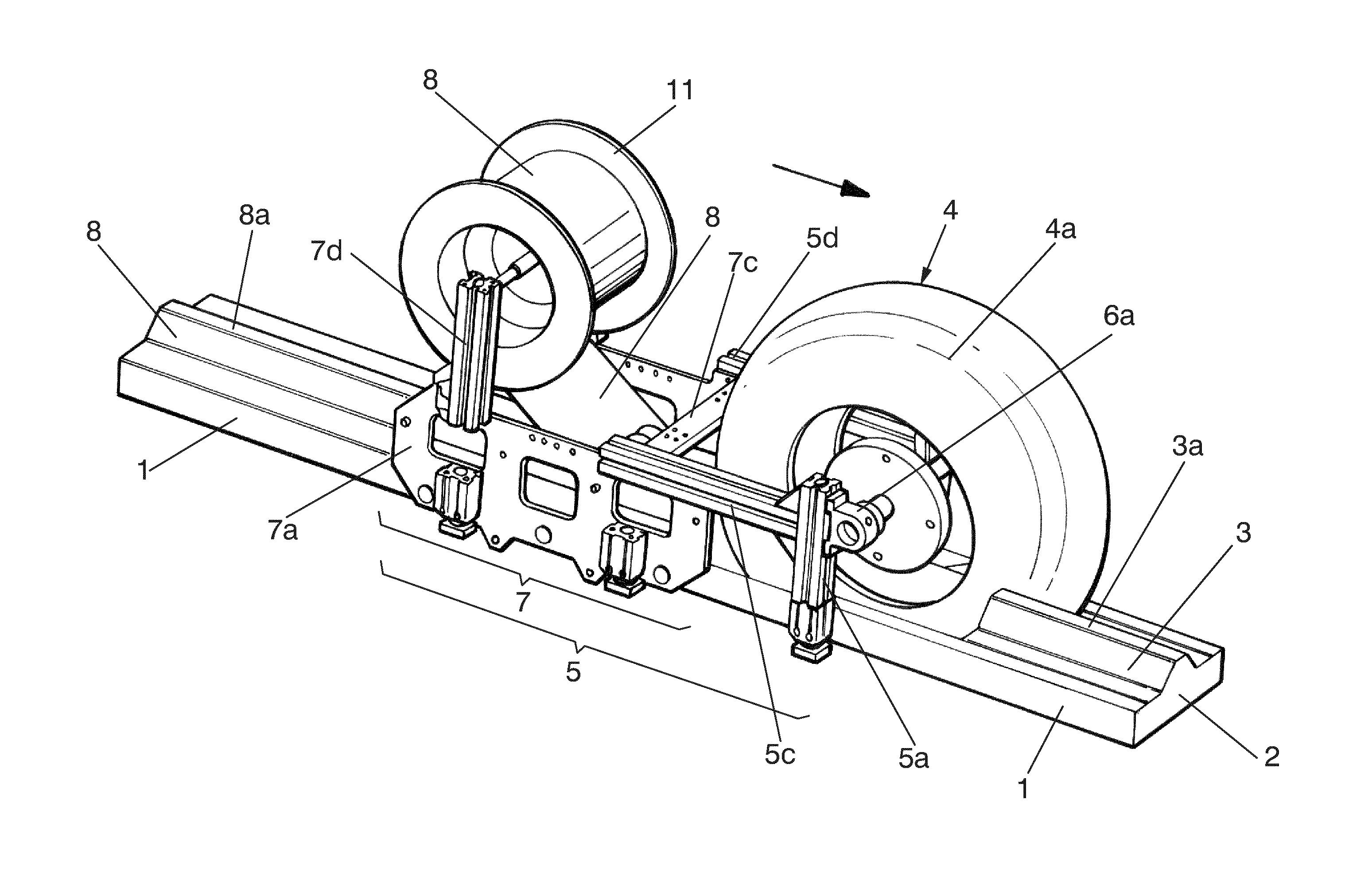
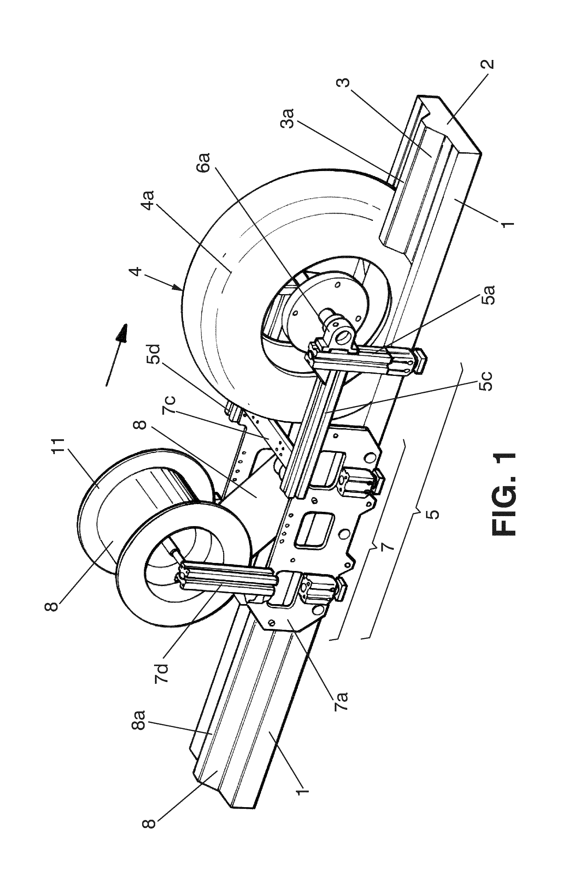
[0059]FIG. 1 is a front-side perspective view of the forming system according to a the present invention;

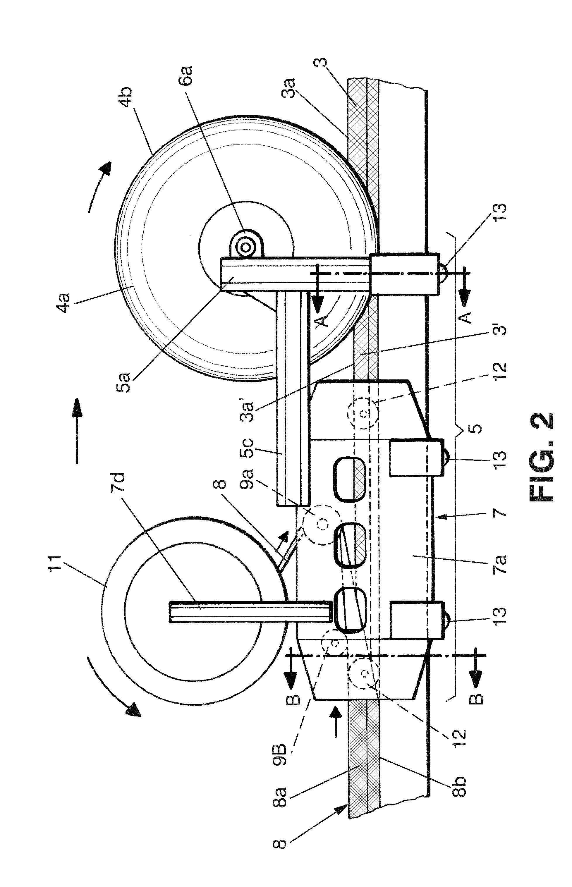
[0060]FIG. 2 is a simplified side elevational view of the forming system shown in FIG. 1.

[0061]FIG. 3 is a simplified upper plan view of the forming system shown in FIG. 1;

[0062]FIG. 4 is a cross-section view of the system along line A-A appearing in FIG. 2;

[0063]FIG. 5 is a cross-section view of the system along line B-B appearing in FIG. 2;

[0064]FIG. 6 is a front perspective view of an embodiment of a mandrel element on which a shaped laminar material is superimposed.

[0065]FIG. 7 is a simplified view of an embodiment of a heat exchange fluid circuit for the system according to the invention

second embodiment

[0066]FIG. 8 is a simplified side elevational view of the forming system according to the present invention;

[0067]FIG. 9 is an upper plan view of the forming system shown in FIG. 8;

[0068]FIG. 10 is a cross-section view along line C-C appearing in FIG. 9;

[0069]FIG. 11 is a front perspective view of an embodiment of a multipurpose cover integrating the thermal blanket and vacuum bag functions;

third embodiment

[0070]FIG. 12 is a simplified side elevational view of the present invention;

[0071]FIG. 13 is a front-side perspective view of the compacting and forming elements present in said third embodiment;

[0072]FIG. 14 is a side elevational view corresponding to FIG. 13;

[0073]FIG. 15 is a rear-side perspective view corresponding to FIG. 13;

[0074]FIG. 16 is a partial upper plan view based on FIG. 13;

[0075]FIG. 17 is a rear-side perspective view of the positioning system of the thermal blanket present in the embodiment of FIG. 12;

[0076]FIG. 18 is a rear-side perspective view of the placement system for placing the laminar band and of the positioning system for positioning the thermal blanket present in the embodiment of FIG. 12;

[0077]FIG. 19 is a cross-section view along line E-E shown in FIG. 12;

[0078]FIG. 20 is a cross-section view along line D-D shown in FIG. 12;

[0079]FIG. 21 is a view of detail I indicated in FIG. 12;

[0080]FIG. 22 is a rear-side perspective view based on FIG. 21;


PUM

PropertyMeasurementUnit
diameteraaaaaaaaaa
diameteraaaaaaaaaa
diameteraaaaaaaaaa

Abstract

The invention relates to a system for shaping laminar composite materials, comprising a base (1) with at least one longitudinal mandrel element (2) comprising a shape to be given to a stack of composite material (3) arranged on the mandrel element (2) for obtaining a formed stack (3′) of composite material, and at least one pressure rolling forming device (4) assembled in a support carriage (5) such that it is capable of placing the pressure rolling forming device (4) in at least one position in which it rolls over the stack of composite material (3) pressing it against the mandrel element (2) for forming it and obtaining the formed stack (3′), the pressure rolling forming device (4) comprising a rolling hollow cover (4a) made of elastically flexible material with a tread (4b), and the rolling hollow cover (4a) being susceptible to containing: a fill fluid at a fill pressure and / or a plurality of particles (27) which allow the tread (4b) to elastically adapt to the shape of the mandrel element (2) and exert a chosen pressure on the stack of composite material (3).

Description

OBJECT OF THE INVENTION[0001]The present invention relates to a system for forming stacks of composite materials; where said system has an application in the technical field of systems for forming stacks of preimpregnated composite material, particularly in the sector of systems for the continuous production of shapes of these stacks.[0002]The purpose of this system is obtaining a device capable of automating the process for forming stacks of composite materials with a high surface quality level due to the steps and physical entities making it up, and where such number of entities and steps are extremely flexible when forming complex geometries of said stacks of composite materials.BACKGROUND OF THE INVENTION[0003]By way of introduction, it is known that the parts obtained from stacks of composite material (composites), such as for example those formed by sheets of resin preimpregnated carbon fibers or glass fibers (prepregs), are widely used in the industry, for example as componen...

Claims


Application Information

Patent Timeline
Patent Type & Authority Applications(United States)
IPC IPC(8): B32B37/10
CPCB29C70/388B29C70/504B32B37/10B29D99/0007B29C70/386B29D99/0003Y10T156/14B29C70/541
Inventor BRUFAU REDONDO, JORDISOLA LORENTE, ANTOI
Owner APPLUS SERVICIOS TECHCOS
Why Eureka
Try Eureka