Image display system and image information transmission method

a technology of image information transmission and display system, which is applied in the field of image display system, can solve the problems of reducing the display quality of moving pictures, difficult to cope with an increase in display frequency, and approaching the upper limit of display frequency, so as to reduce information and low degree of recognition

Inactive Publication Date: 2005-11-17
HIYAMA IKUO +7
View PDF13 Cites 26 Cited by
  • Summary
  • Abstract
  • Description
  • Claims
  • Application Information

AI Technical Summary

Benefits of technology

[0016] A first object of the present invention is to provide an image transmission method conformable to the high definition image display and high speed moving picture display at the same

Problems solved by technology

That is, with the conventional driving method for the image display method or the image display unit, it is difficult to cope with an increase in the display frequency that is caused by the higher definition display, due to a signal delay on the wiring, shortage of the writing time into each pixel, and increased scanning frequency.
According to this report, since there is inconsistency between a moving picture that is in hold luminescent and the movement of the line of sight pursuing the moving picture, some blur occurs in the moving picture, degrading the display quality of moving picture.
However, with the driving method for the image display method or the image display unit that is employed at present, as already described, the increase in display frequency has approached its upper limit.
Also, there was no description for the method of effecting both high definition and high

Method used


Image

  • Image display system and image information transmission method
  • Image display system and image information transmission method
  • Image display system and image information transmission method

Examples


embodiment 1

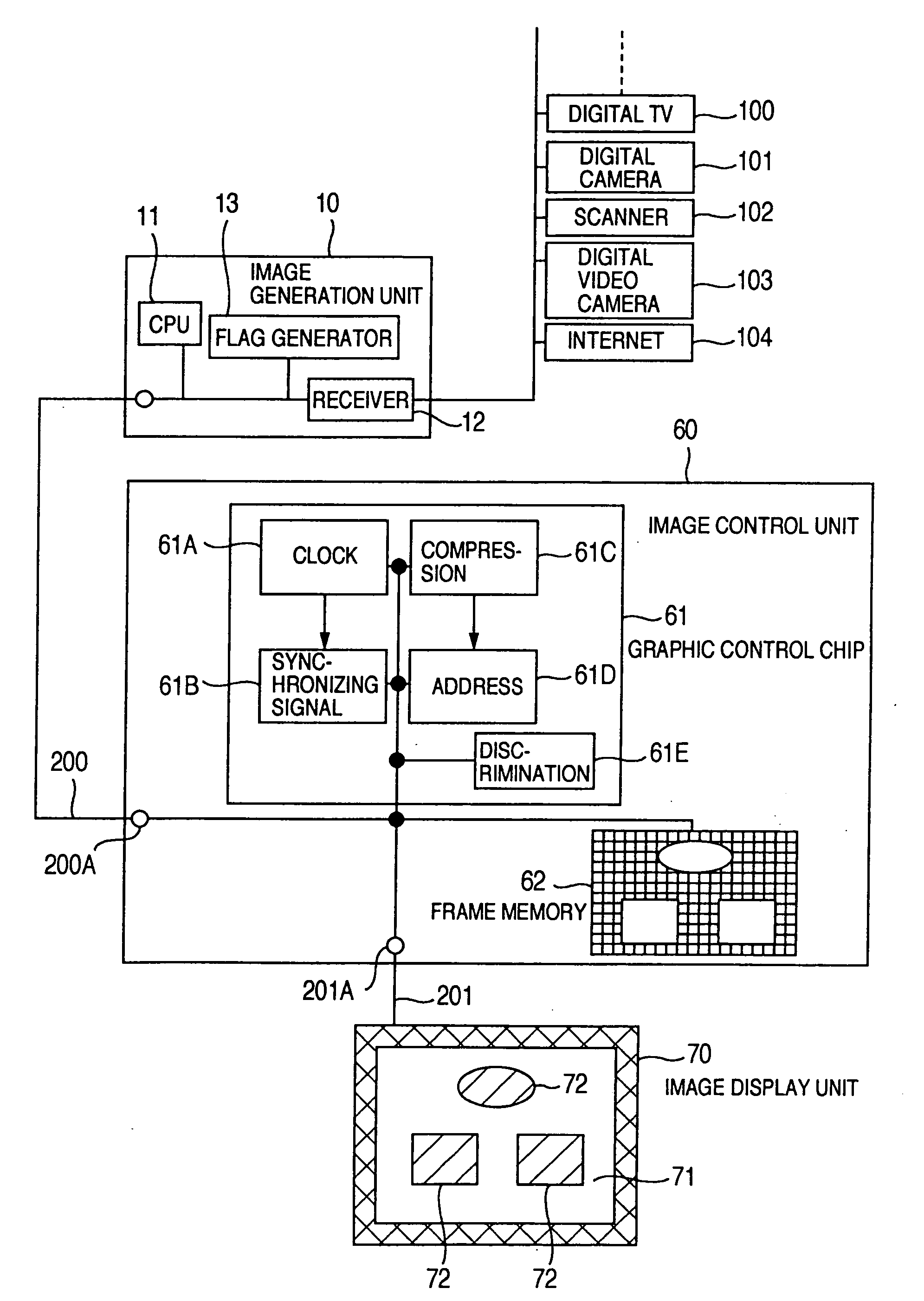
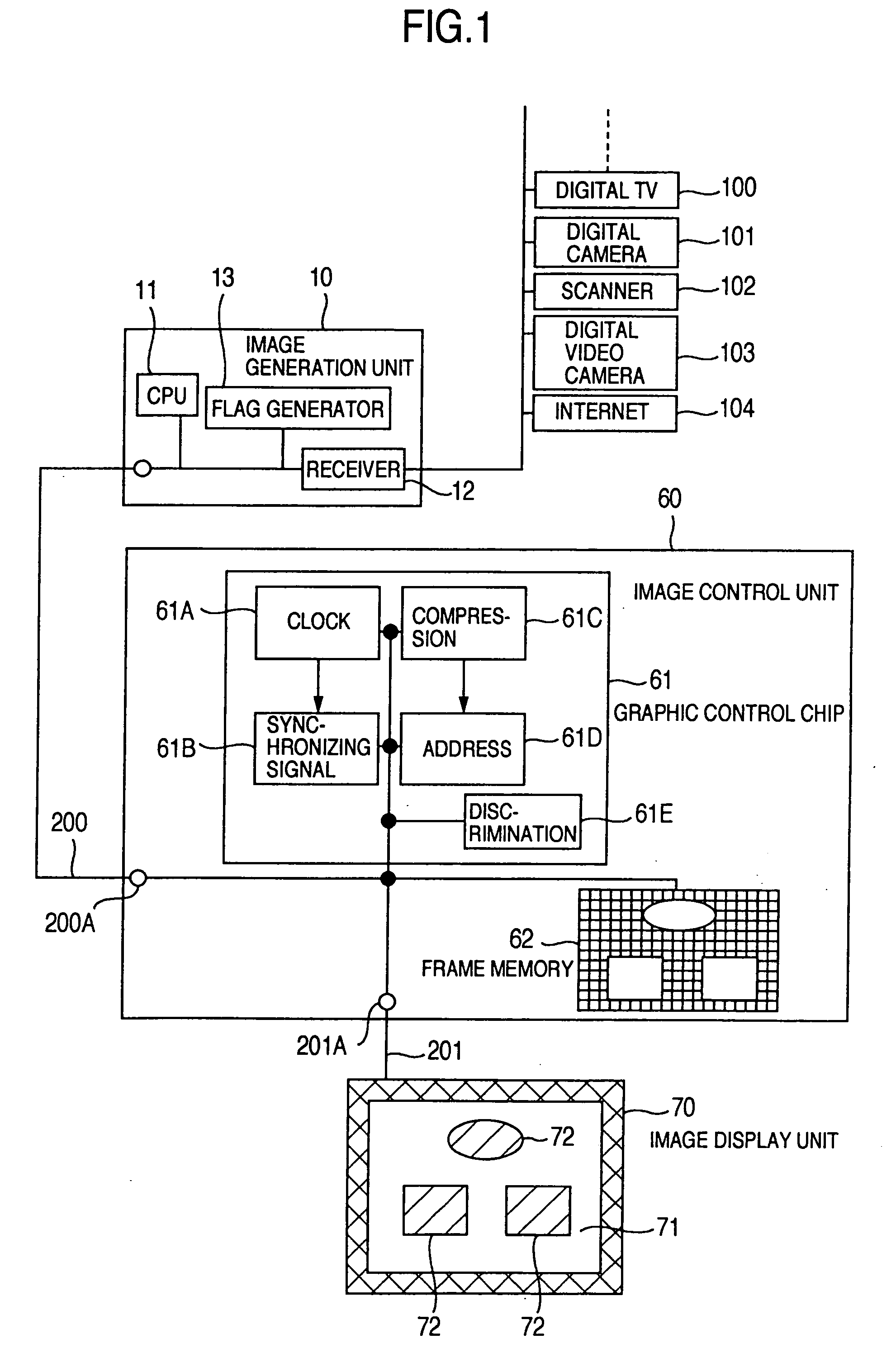
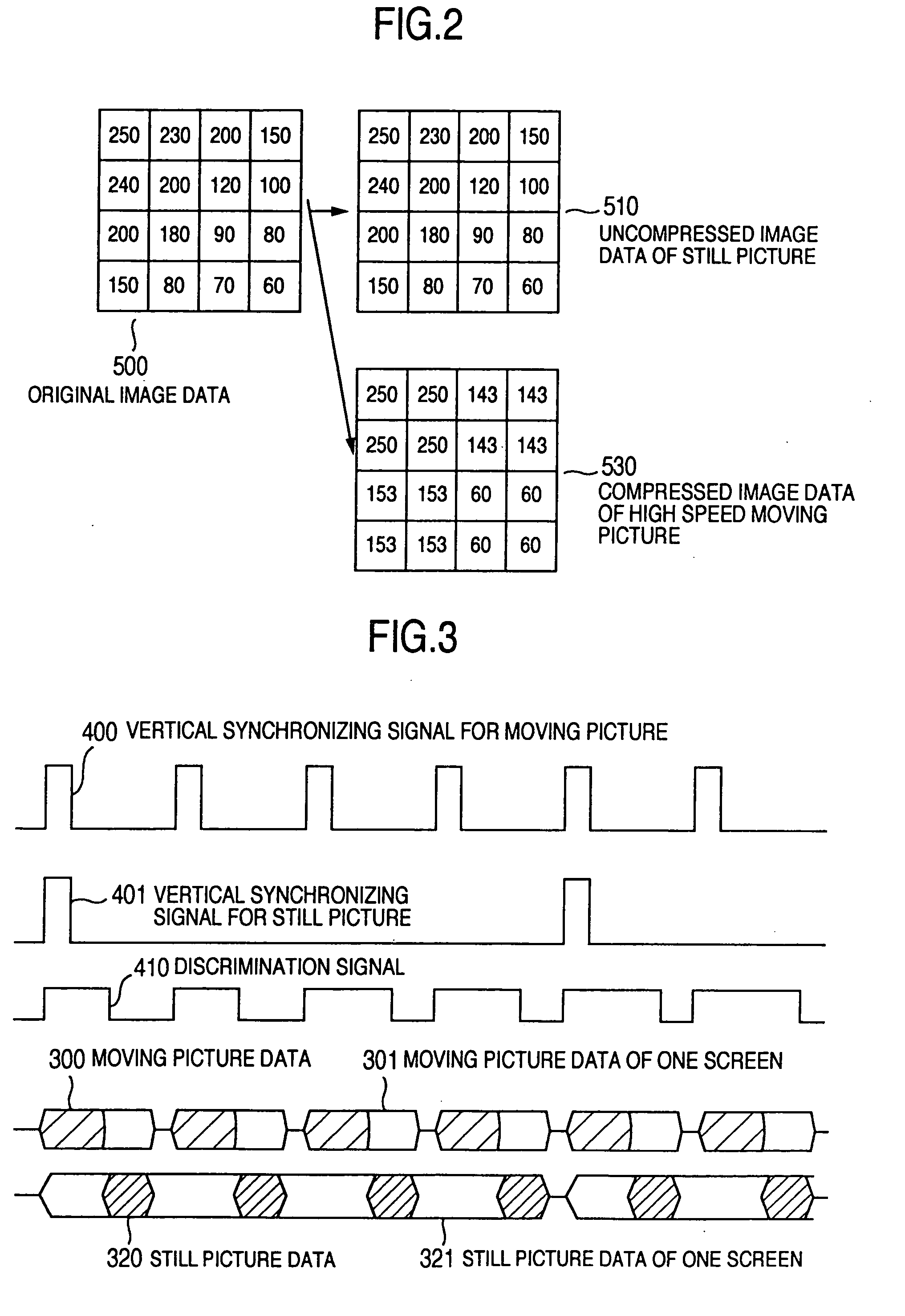
[0057] First of all, an image compression method according to an embodiment of the present invention will be described below by reference to FIG. 2. Herein, FIG. 2 shows an example of 4×4 pixels (m=16 pixels), in which the number within each pixel indicates a gray scale level of pixel by 0 to 255 in the display having 256 gradations. For example, when the original image data 500 is discriminated as the still picture in a unit of block by the block state discrimination circuit 61E, the image conversion (16 image data) is not performed, like the still picture uncompressed image data 510, because the definition is important for the still picture, or the image compression is made with a smaller number of gradations, without decreasing the definition, as will be described later. On one hand, when the original image data 500 is discriminated as the moving picture by the block state discrimination circuit 61E, the resolution is reduced in a unit of 2×2 pixels, for example, and four image d...

embodiment 2

[0062] Referring not to FIG. 5, a second embodiment in which the transmission sequence of image information is different from that of the embodiment 1 will be described below.

[0063] The synchronizing signal generation circuit 61B of FIG. 1 generates a moving picture vertical synchronizing signal 400 and a still picture vertical synchronizing signal 401 with a quadruple period, and further the block discrimination circuit 61E generates a discrimination signal 410 from the image information for each block. In accordance with this discrimination signal 410 having three levels, the moving picture data 300, the slow speed moving picture data 310 and the still picture data 320 are transmitted. Herein, the slow speed moving picture data means the moving picture with small movement, and is transmitted as an intermediate picture between the moving picture and the still picture. As in FIG. 3, the still picture data 320 corresponds to the still picture vertical synchronizing signal 401, the d...

embodiment 3

[0064] Referring not to FIG. 6, a third embodiment as the special case in the transmission sequence of image information in the embodiments 1 and 2 will be described below. In the embodiments 1 and 2, when the entire area of one screen is a moving picture area, the moving picture data 300 is transmitted for every frame in accordance with the moving picture vertical synchronizing signal 400 to display the moving picture on the entire area of screen. Like the embodiments 1 and 2, the clear moving picture can be displayed at half resolution at high speed. On one hand, when the entire area of one screen is a still picture, the still picture data 320 is transmitted for every frame in accordance with the still picture vertical synchronizing signal 401 once per four moving picture vertical synchronizing signals 400, to display the still picture at high definition on the entire area of screen.


PUM


Abstract

To provide a display device capable of displaying a moving picture with high definition and at high speed. An image display system includes: an image display unit; and a control unit. The control unit has: a block discrimination circuit portion; an image processing portion; a storage portion; and a synchronizing signal generation portion. The block discrimination circuit portion discriminates a moving picture or a still picture to process the image information in accordance with the discriminated result, in which the number of gradations for the image information processed when the discriminated result is the moving picture is lower than when the discriminated result is the still picture. Thereby, the high definition image display and the high speed moving picture display can be effected by reducing the information with lower degree of recognition.

Description

[0001] The present application is a divisional application of application Ser. No. 09 / 961,176, filed Sep. 24, 2001, the contents of which are incorporated herein by reference.BACKGROUND OF THE INVENTION [0002] The present invention relates to an image display system, and more particularly to an image information transmission method in which the resolution, the number of gray scale level, and the rewriting speed for the display are changeable within the screen. [0003] In recent years, an image display apparatus has become thinner and lighter, a flat panel display such as a liquid crystal display, a PDP (Plasma Display Panel), and an EL display (Electroluminescent Display) has rapidly spread, in place of a CRT that was mainly employed for the image display apparatus. Also, the technical development of an FED (Field Emission Display) has also rapidly progressed. Moreover, the display of high definition, high speed moving picture has become requisite, along with the spread of personal c...

Claims


Application Information

Patent Timeline
IPC IPC(8): G06F3/14G02F1/133G06Q30/04G06Q30/06G06Q50/00G09G3/00G09G3/20G09G3/36G09G5/00G09G5/36H04N5/38H04N5/44H04N5/66H04N7/16H04N7/46H04N21/2543H04N21/431
CPCG06F3/14G09G2340/02G09G2340/0407H04N19/59H04N19/12H04N19/124H04N19/137H04N19/103G09G5/36
Inventor HIYAMA, IKUOYAMAMOTO, TSUNENORIKONNO, AKITOYOTSUMURA, MAKOTOKANEKO, YOSHIYUKIMIKAMI, YOSHIROINUZUKA, TATSUKITOYODA, YASUTAKA
Owner HIYAMA IKUO
Why Eureka
Try Eureka