Control circuit for an electromagnetic drive

a control circuit and electromagnetic technology, applied in power conversion systems, electrical apparatus, relays, etc., can solve the problems of reducing limiting the charging end voltage, etc., to reduce the required operating coil variant, reduce costs, and reduce the dependence of charging and discharging processes on magnitude.

Active Publication Date: 2005-11-17
KLOCKNER-MOELLER GMBH
View PDF3 Cites 30 Cited by
  • Summary
  • Abstract
  • Description
  • Claims
  • Application Information

AI Technical Summary

Benefits of technology

[0010] The proposed control circuit does not need any complex digital means, especially no microcontroller, and is suitable for both DC and AC operating mechanisms, and especially for lower-power electromagnetic operating mechanisms. Since the pickup time and the holding current can assume low values, the control circuit of the present invention also allows the use of AC electromagnetic operating mechanisms that have low-resistance operating coils and which, without using the proposed control circuit, would otherwise only be suitable for AC operation. This allows the manufacture of electromagnetic switching devices to be limited to only AC operating mechanisms, thereby making it possible to reduce the necessary operating coil variants, and thus to markedly reduce costs.
[0011] The timer can advantageously be implemented as a simple, integrating or differentiating RC element (also referred to as a “low-pass filter” or “high-pass filter”). The combination with a voltage-limiting device, for example, a Zener diode, results in a limitation of the charging end voltage, thereby considerably reducing the dependence of the charging and discharging processes on the magnitude of the operating voltage.
[0012] The controllable voltage source includes a voltage-limiting circuit combined with a threshold circuit and is therefore inexpensive. When using an integrating timer, usually, the charge voltage increasing at the charging capacitor of the RC element is evaluated by the threshold switch as the controlling value for the termination of the pickup phase. When using a differentiating timer, the threshold switch usually evaluates the voltage decreasing at the discharge resistor as a result of the discharging current.
[0013] Free-wheeling means, such as a Zener diode, which are placed in parallel with the switching path of the second switching means, provide a fast demagnetization of the operating coil during de-energization, possibly in cooperation with other free-wheeling means.

Problems solved by technology

The combination with a voltage-limiting device, for example, a Zener diode, results in a limitation of the charging end voltage, thereby considerably reducing the dependence of the charging and discharging processes on the magnitude of the operating voltage.

Method used


Image

  • Control circuit for an electromagnetic drive
  • Control circuit for an electromagnetic drive
  • Control circuit for an electromagnetic drive

Examples


Embodiment Construction

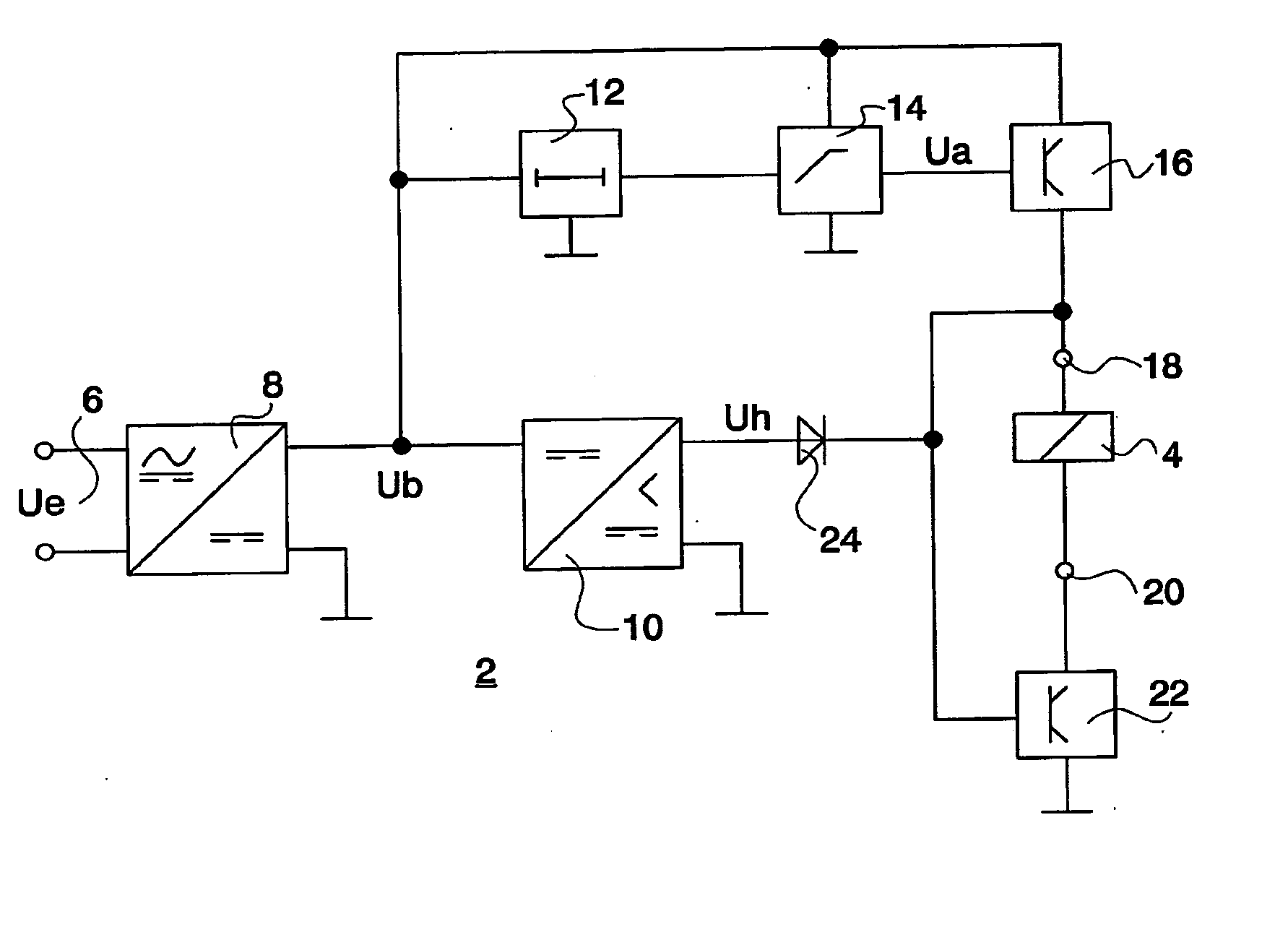
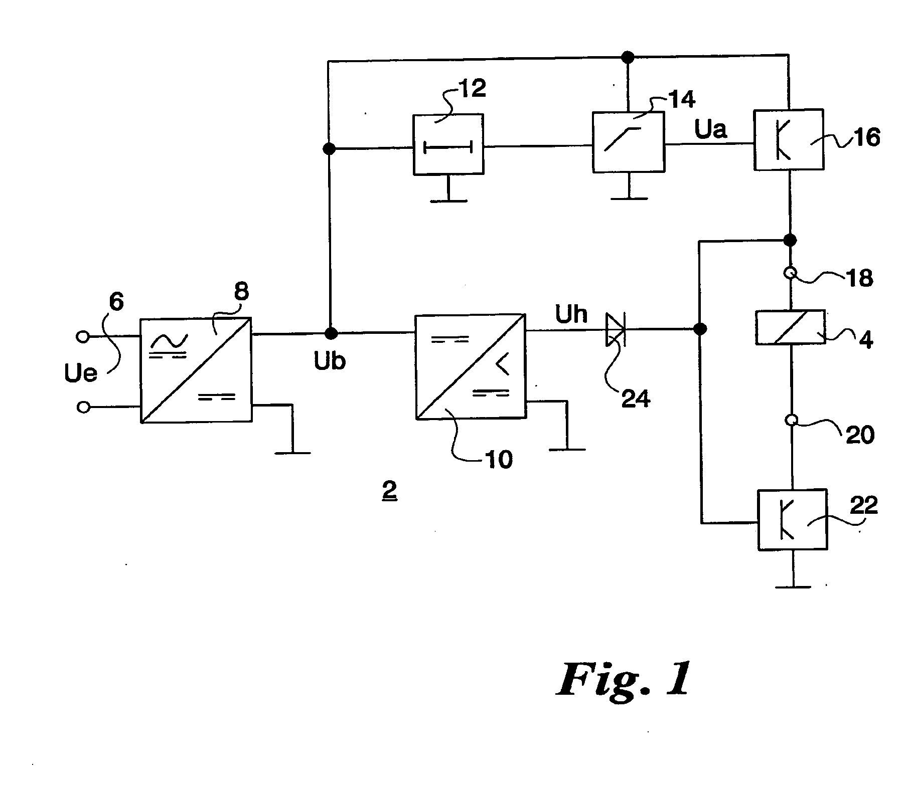
[0017]FIG. 1 shows a control circuit 2 for an operating coil 4 of an electromagnetic operating mechanism (not specifically shown) of an electromagnetic switching device; the control circuit being operated by a control voltage Ue via a control input 6. The control voltage Ue applied can optionally be a DC voltage or an AC voltage. When control voltage Ue is applied, a smoothed operating voltage Ub is present at the output of a rectifier circuit 8; the smoothed operating voltage being used, inter alia, for power supply to control circuit 2 and to operating coil 4. A d.c. voltage converter 10 downstream of rectifier circuit 8 converts operating voltage Ub to a significantly lower smoothed holding voltage Uh. After control voltage Ue has been applied, the rapidly increasing operating voltage Ub triggers a timer 12, the time behavior of which controls the duration of the pickup phase of control circuit 2. Triggered timer 12 activates a voltage source 14 which, when in the activated state...


PUM


Abstract

The invention relates to a control circuit (2) for an electromagnetic drive. Said circuit contains first and second electronic switching elements (16 to 22), which in conjunction with a timing element (12) subject the drive coil (4) to a corresponding direct current in the starting phase or in the maintenance phase. A starting current (Ua) and a maintenance current (Ub) are provided by means of a current source (14) that is controlled by the timing element (12) and a direct current converter (10) with downward control.

Description

DESCRIPTION [0001] 1. Field of the Invention [0002] The present invention relates to a control circuit for an electromagnetic operating mechanism, in particular, the operating mechanism of an electromagnetic switching device. The electromagnetic operating mechanism generally includes an operating coil, a magnetic core, and an armature. [0003] 2. Background Information [0004] An electronic drive control for a contactor operating mechanism is described in German Publication DE 299 09 901 U1. The drive control essentially includes a rectifier circuit supplied via control inputs, a series circuit which is composed of the operating coil and a pulse-width controlled transistor switch and is supplied by the rectifier circuit, two voltage divider circuits which scan the output of the rectifier circuit and are isolated on the input side by an isolation diode, as well as an electronic circuit including a microprocessor and two memories. Control signals for the pickup and holding modes of the ...

Claims


Application Information

Patent Timeline
Patent Type & Authority Applications(United States)
IPC IPC(8): H01H47/04H01H47/32
CPCH01H47/32H01H47/04
Inventor MELCHERT, WILHELMSCHMITZ, GERD
Owner KLOCKNER-MOELLER GMBH
Why Eureka
Try Eureka