Image recording apparatus and its control method

Active Publication Date: 2005-11-17
OKI ELECTRIC IND CO LTD
View PDF5 Cites 25 Cited by
  • Summary
  • Abstract
  • Description
  • Claims
  • Application Information

AI Technical Summary

Benefits of technology

[0009] It is an object of the invention to provide an image recording apparatus and its control method, in which a transfer start position of a shee

Problems solved by technology

The conventional image recording apparatus and the technique of the above Offi

Method used


Image

  • Image recording apparatus and its control method
  • Image recording apparatus and its control method
  • Image recording apparatus and its control method

Examples


embodiment 1

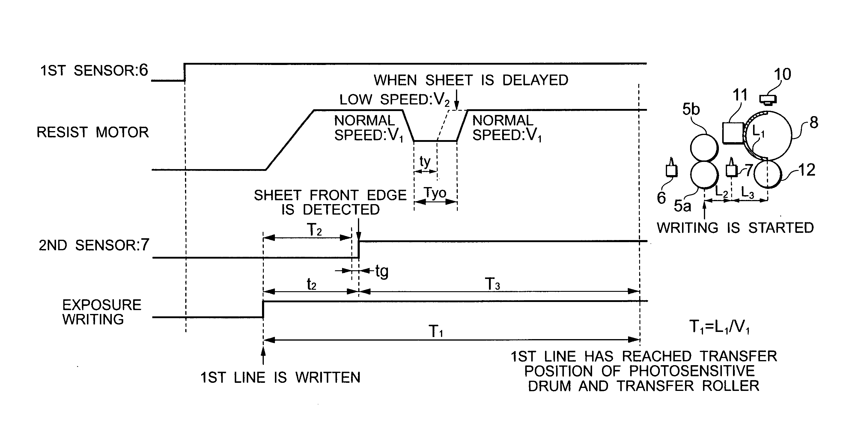
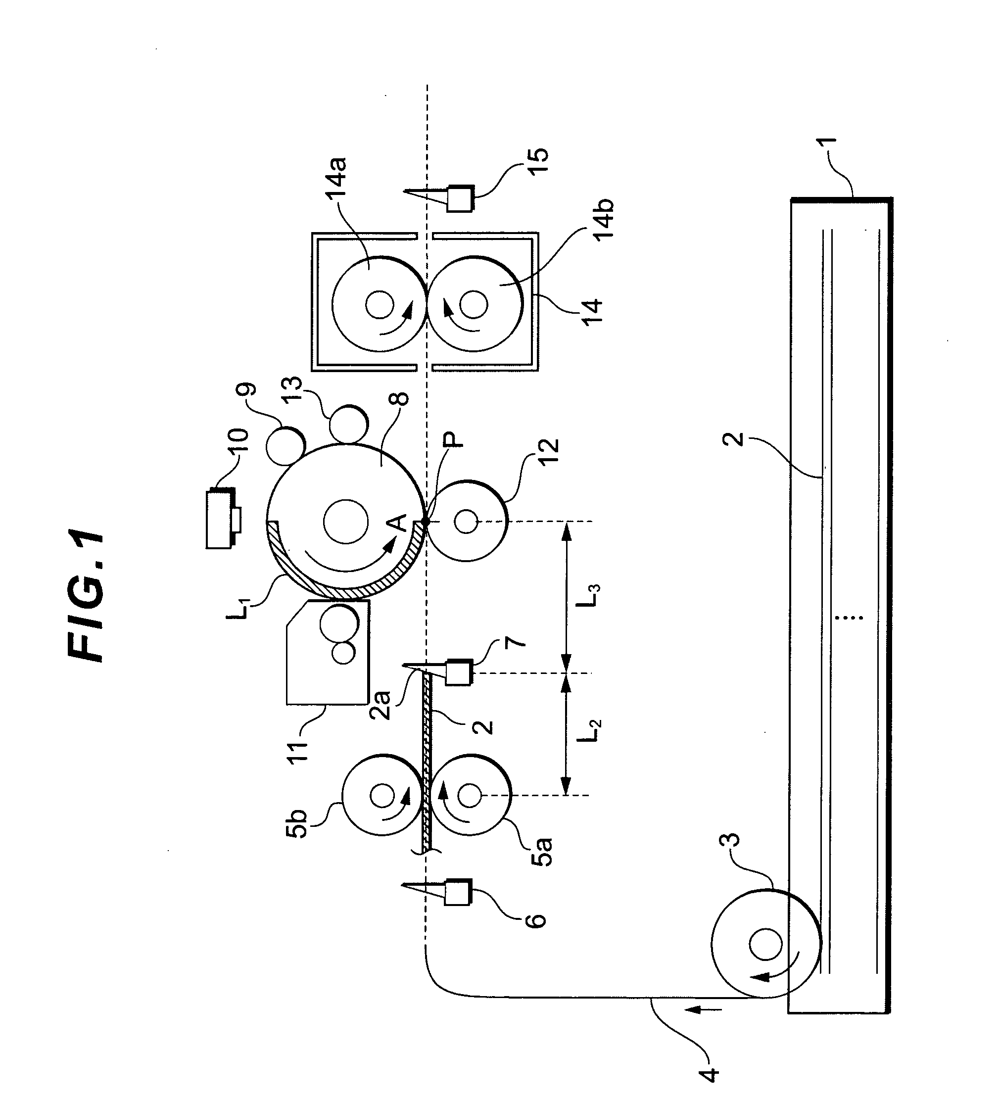
[0050]FIG. 1 is a side elevational view showing a construction of the embodiment 1. Sheets 2 as recording media set in a sheet cassette 1 are fed out one by one to the outside of the cassette by a paper feed roller 3. A pair of resist rollers 5a and 5b for conveying the sheet 2 fed out from the sheet cassette 1 are arranged as conveying members on a conveying path 4 subsequent to the paper feed roller 3. A first sensor 6 as medium detecting means is arranged on the conveying path 4 of an upstream side just before the resist rollers 5a and 5b, thereby detecting passage of a front edge and a rear edge of the sheet 2 fed out from the sheet cassette 1. A second sensor 7 as medium detecting means is also arranged on the conveying path 4 of a downstream side of the resist rollers 5a and 5b, thereby detecting the front edge of the sheet 2 which is conveyed by the resist rollers 5a and 5b and passes. A photosensitive drum 8 as an image holding material serving as a principal portion of the ...

embodiment 2

[0082] The embodiment 2 as an application example of the embodiment 1 mentioned above will now be described with reference to FIGS. 7 and 8. Component elements common to those of the units and apparatuses of the embodiment 1 are designated by the same reference numerals and their detailed description is omitted here.

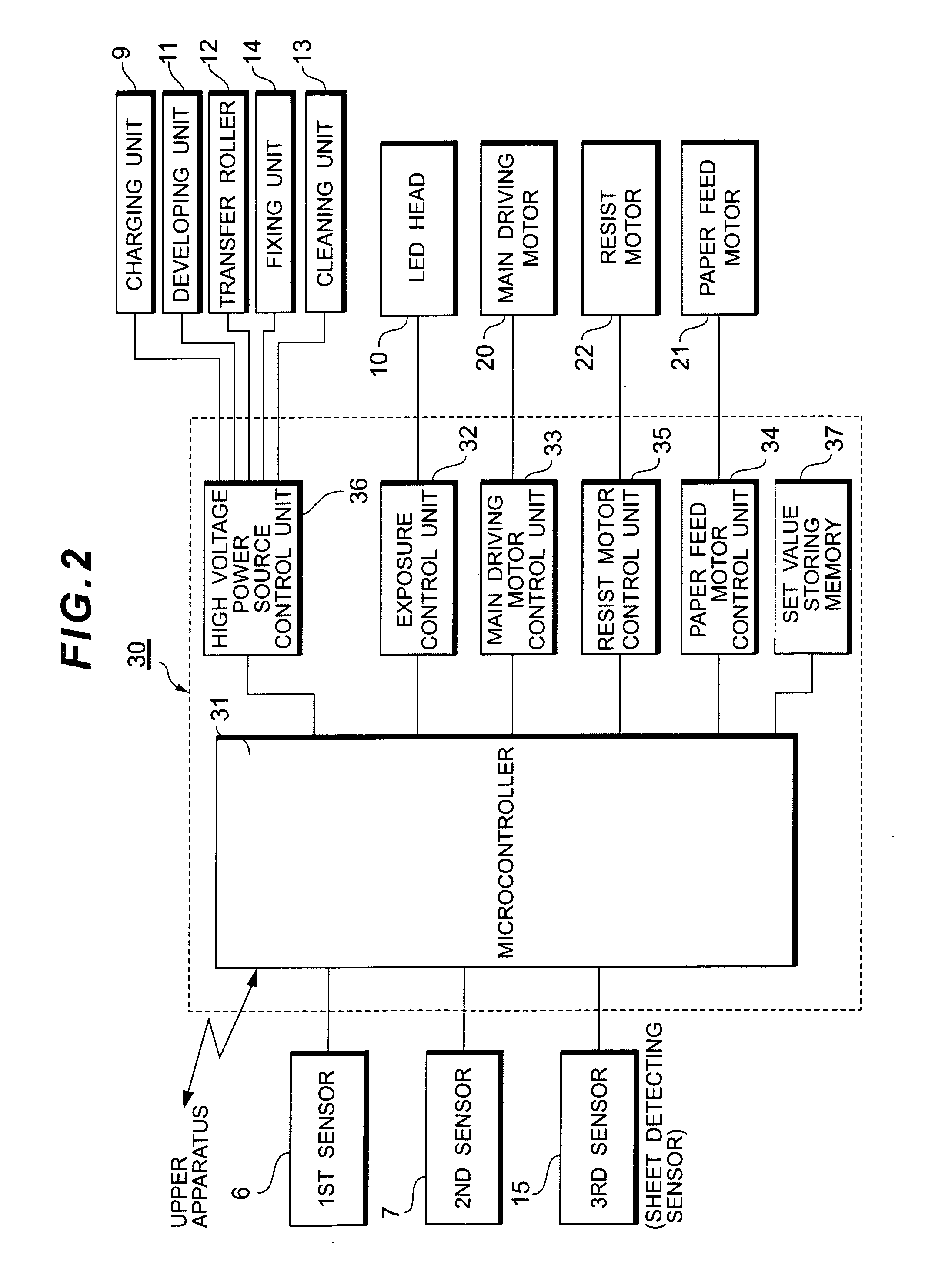
[0083] As shown in a functional block diagram of FIG. 7, a motor current setting unit 38 is newly provided for the control apparatus 30 and connected to the microcontroller 31. The motor current setting unit 38 is connected to the microcontroller 31 and also connected to the resist motor control unit 35. For example, a D / A converter can be used as a motor current setting unit 38. The motor current setting unit 38 receives an instruction signal from the microcontroller 31 and varies an output voltage (output current) to the resist motor control unit 35. The resist motor control unit 35 changes a phase current value of the motor on the basis of an output of the motor curr...


PUM


Abstract

After a skew of a sheet as a recording medium is corrected by correcting a sheet curve, exposure writing on a photosensitive drum is started synchronously with re-driving of resist rollers. When a sheet front edge is detected by a sensor, sheet conveyance is continued while adjusting a sheet conveying speed when an exposure start position reaches a transfer position at a pressure contact point between the drum and a transfer roller, thereby adjusting the time of arrival at the transfer position. A time/distance interval between the preceding and subsequent sheets are shortened, a conveying path is shortened, and the whole apparatus is miniaturized. Print processing efficiency is raised and stable printing without a variation is executed. A transfer start position of the sheet is made to accurately coincide with the exposure start position of the drum, thereby realizing a high print processing speed.

Description

BACKGROUND OF THE INVENTION [0001] 1. Field of the Invention [0002] The invention relates to an image recording apparatus such as printing apparatus, facsimile apparatus, copying apparatus, or the like and its control method. [0003] 2. Related Background Art [0004]FIG. 11 is a schematic diagram showing an example of an image recording apparatus. Sheets 41 as recording media are enclosed in a sheet cassette 40. A paper feed roller 42 is rotated, thereby feeding out the sheets 41 one by one. The sheet is conveyed to an image forming mechanical unit by resist rollers 43 arranged on a conveying path. A skew correction to correct a curve or the like of the sheet 41 is made by the resist rollers 43. After that, the sheet 41 is conveyed to a photosensitive drum 46 of the image forming mechanical unit. [0005] A first sensor 44 and a second sensor 45 as sheet detecting means are arranged on a conveying path on an upstream side and a downstream side of the resist rollers 43, respectively, the...

Claims


Application Information

Patent Timeline
IPC IPC(8): G03G15/00G03G21/14
CPCG03G15/6567G03G15/6564
Inventor TAKAHASHI, ZENJI
Owner OKI ELECTRIC IND CO LTD
Why Eureka
Try Eureka