Single fuel cell system

a fuel cell and single-cell technology, applied in the field of single-cell fuel cell systems, can solve the problems of affecting fuel cell performance, less efficient operation of fuel cell systems, cathode flooding, etc., and achieve the effects of reducing electrical parasitic loss, reducing overall efficiency, and reducing the size of the total system

Inactive Publication Date: 2005-11-17
MTI MICROFUEL CELLS
View PDF9 Cites 14 Cited by
  • Summary
  • Abstract
  • Description
  • Claims
  • Application Information

AI Technical Summary

Benefits of technology

[0020] Several embodiments of the pump and valve sub-system of the present invention also allow for a stack purge state that can be activated upon system shut-down or as a recovery procedure should the fuel concentration in the stack become above or below acceptable limits or where the pressure within the fuel cell is greater than desired, or where it is desirable to put the fuel cell stack in a freeze tolerant state. The stack purge functionality of the system of the present invention benefits overall efficiency, stack control and provides the ability to put the system in a freeze-tolerant state.
[0021] A liquid / gas separator can be employed to remove undesired gas bubbles from the fluid conduits in some embodiments of the invention. An optional concentration sensor may be used to determine fuel concentration in the anode recirculation loop. In some embodiments, the system can also be operated without a concentration sensor. A pressure sensor can be included to determine if the recirculation loop is full, partially full or empty. A fuel filter may optionally be used to protect the pump and valves from any debris that may be present in the fuel mixture, the water or other effluents traveling throughout the conduits of the system. The single pump and valve sub-system yields a smaller total system size and lower electrical parasitic loss than for example, a in multi-pump design.

Problems solved by technology

However, because fuel processing is complex and generally requires costly components which occupy significant volume, reformer based systems are more suitable for comparatively high power applications.
However, too much water can lead to cathode flooding.
However, the multiple pumps that are needed to carry the various solutions throughout the fuel cell can lead to parasitic losses that ultimately result in a less efficiently operating fuel cell system.
Another challenge arises in a system containing a fuel cell stack when it is necessary to purge the stack of fluids.
Ambient environmental conditions are also a factor in the dissipation of heat, and affect fuel cell performance, particularly in sub-freezing ambient environments.

Method used


Image

  • Single fuel cell system
  • Single fuel cell system
  • Single fuel cell system

Examples


Embodiment Construction

Fuel Delivery

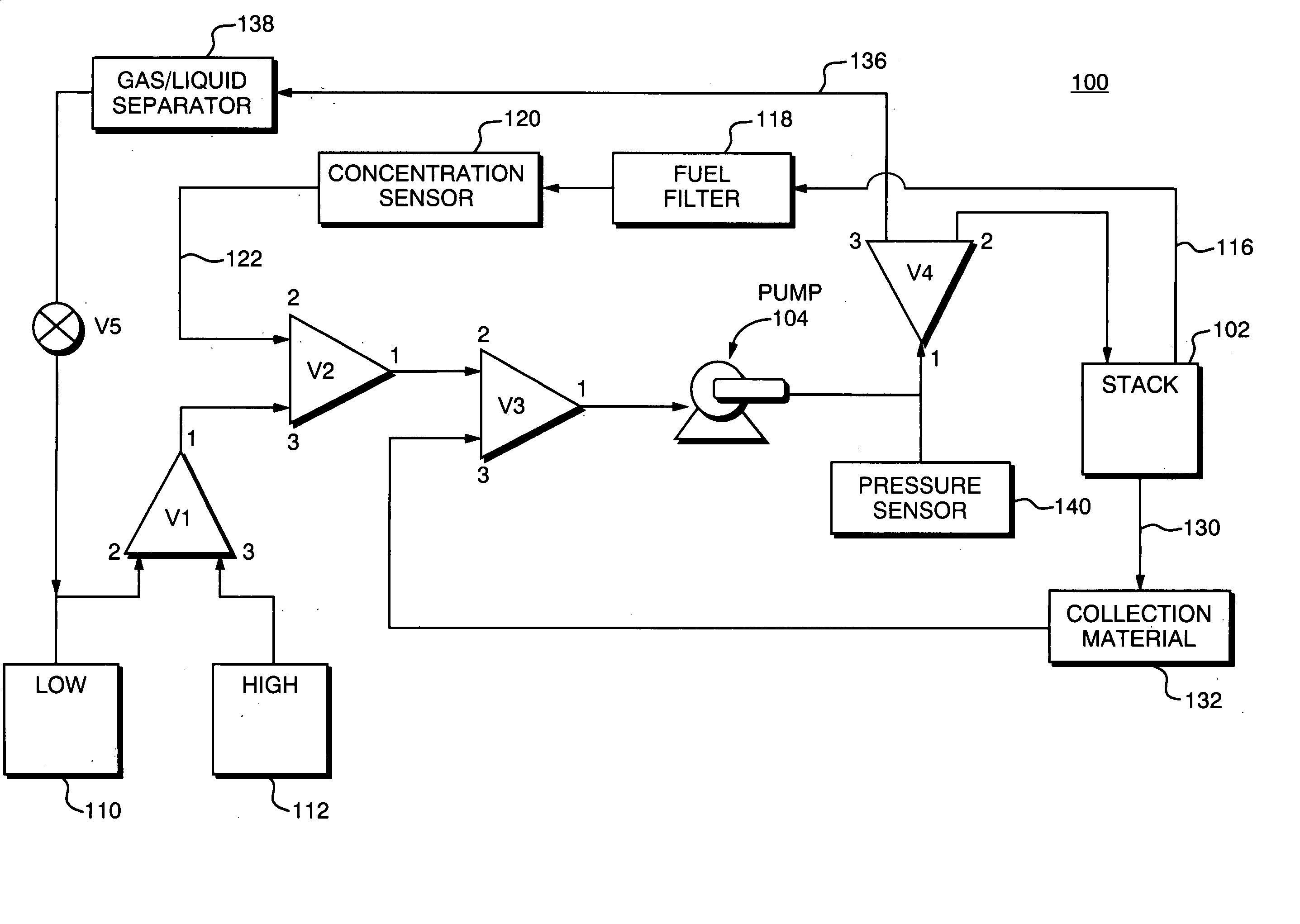
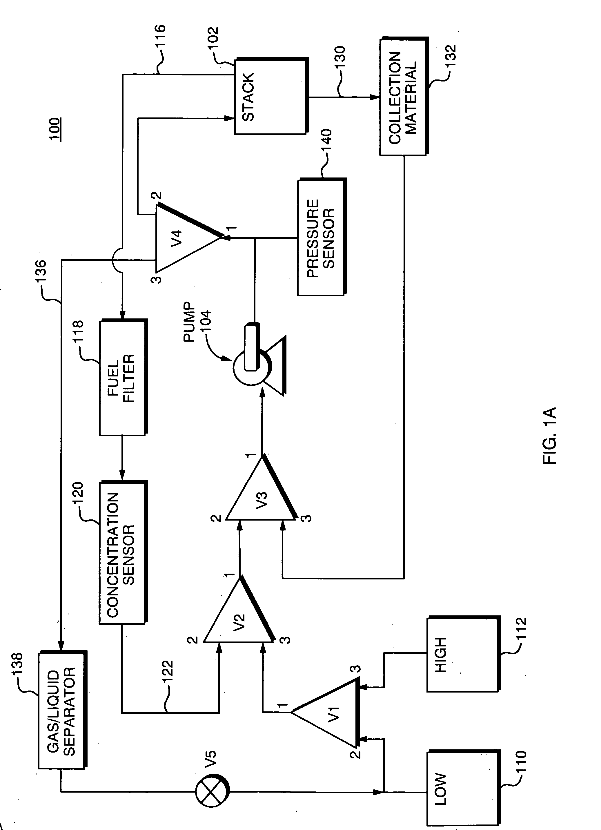
[0029] A first embodiment of the invention is illustrated in FIG. 1A, which depicts a fuel cell system 100 that includes a fuel cell stack 102. The fuel cell stack preferably includes a bipolar fuel cell plate with integrated gas separation, including but not limited to that set forth in commonly owned U.S. patent application Ser. No. 10 / 384,095, by DeFilippis, for a Bipolar Plate or Assembly having Integrated Gas-Permeable Membrane, which is incorporated herein by reference. Fuel is delivered to the fuel cell stack 102, in accordance with the present invention by the single pump 104 that is coupled to the valve sub-system, which, in the embodiment of FIG. 1A, includes five valves V1-V5. The valves are controlled by a processor (not shown) that will retrieve information regarding system operation and will issue commands signaling the settings for valves V1-V5, depending upon the current mode of operation of the system. Those skilled in the art will recognize that the ...


PUM

PropertyMeasurementUnit
concentrationaaaaaaaaaa
heataaaaaaaaaa
specific energyaaaaaaaaaa

Abstract

A single pump fuel cell system is provided that has multiple valves that have selective positioning to control fluidic flow throughout a fuel cell system. One of the valves provides for high and low concentration fuel dosing. Another valve or series of valves controls an unreacted fuel recirculation loop leading from the fuel cell. Another valve or series of valves control condensate collection by the fuel cell system, and allows the purging of the anode recirculation loop. Each of the valves is selectable between various positions to place the fuel cell system in a desired operating mode. A heat exchanger may also be employed to dissipate heat as desired out of the fuel cell system. A concentration sensor can also be employed to aid in achieving a desired fuel concentration within the fuel cell system.

Description

BACKGROUND OF THE INVENTION [0001] 1. Field of the Invention [0002] This invention relates generally to fuel cell systems, and more particularly, to techniques for managing fluid flow throughout the fuel cell system. [0003] 2. Background Information [0004] Fuel cells are devices in which electrochemical reactions are used to generate electricity from fuel and oxygen. A variety of materials may be suited for use as a fuel depending upon the materials chosen for the components of the cell. Organic materials in liquid form, such as methanol are attractive fuel choices due to the their high specific energy. [0005] Fuel cell systems may be divided into “reformer-based” systems (i.e., those in which the fuel is processed in some fashion to extract hydrogen from the fuel before the hydrogen is introduced into the fuel cell system) or “direct oxidation” systems in which the fuel is fed directly into the cell without the need for separate internal or external fuel processing. Many currently ...

Claims


Application Information

Patent Timeline
Patent Type & Authority Applications(United States)
IPC IPC(8): H01M8/02H01M8/04
CPCH01M8/04067H01M8/04164H01M8/04171Y02E60/50H01M8/04231H01M8/1011H01M8/04194
Inventor DEFILIPPIS, MICHAEL S.VERELA, GRACIELA I.YETTO, LUKE E.BROWN, KEITH G.
Owner MTI MICROFUEL CELLS
Why Eureka
Try Eureka