Micro-generator implant

a micro-generator and implant technology, applied in the field of internal energy sources, can solve the problems of increased implant size, increased risk, discomfort, etc., and achieve the effect of reducing risk and discomfort to patients, reducing the overall size of the implanted device, and reducing the size of the internal components

Inactive Publication Date: 2005-11-17
SIRIUS IMPLANTABLE SYST
View PDF41 Cites 92 Cited by
  • Summary
  • Abstract
  • Description
  • Claims
  • Application Information

AI Technical Summary

Benefits of technology

[0015] There is therefore a recognized need for, and it would be highly advantageous to have, a system and method of powering an implanted medical device that overcomes these and other problems associated with the various conventional systems. It would be of further advantage to have a system that minimizes the size of components internal to the implanted device necessary for p

Problems solved by technology

Although rechargeable batteries have been successfully employed in a variety of applications, some present day pacemakers and defibrillators use non-rechargeable batteries.
Surgery, with its attendant risks, discomforts, and cost is required when it becomes necessary to replace an implanted medical device.
Longer life for an implant can be achieved by using a larger battery, however, this undesirably increases the size of the implant.
Some implanted medical devices, such as ventricular assist devices, require large amounts of electrical power to operate.
Multiple needle sticks are required to mate the needles with all of the conductive ports, thus potentially increasing discomfort to the patient.
For example, the efficiency of transcutaneously inducing a current in the implanted coil is detrimentally affected if the internal and external coils are not properly aligned or oriented, or if the distance between the external and internal coils is too great.
Because there is no direct physical connection between the external charger and the implanted device to provide feedback, ascertaining whether transmission efficiency is maximized or whether the battery has become fully charged is problematic.
If too great, the temperature increase in the implanted device caused by eddy currents can damage the s

Method used


Image

  • Micro-generator implant
  • Micro-generator implant
  • Micro-generator implant

Examples


Embodiment Construction

[0111] The present invention is a micro-generator implant for providing power within a living body.

[0112] The principles and operation of the micro-generator implant according to the present invention may be better understood with reference to the drawings and the accompanying description.

[0113] Before explaining at least one embodiment of the invention in detail, it is to be understood that the invention is not limited in its application to the details of construction and the arrangement of the components set forth in the following description or illustrated in the drawing. The invention is capable of other embodiments or of being practiced or carried out in various ways. Also, it is to be understood that the phraseology and terminology employed herein is for the purpose of description and should not be regarded as limiting.

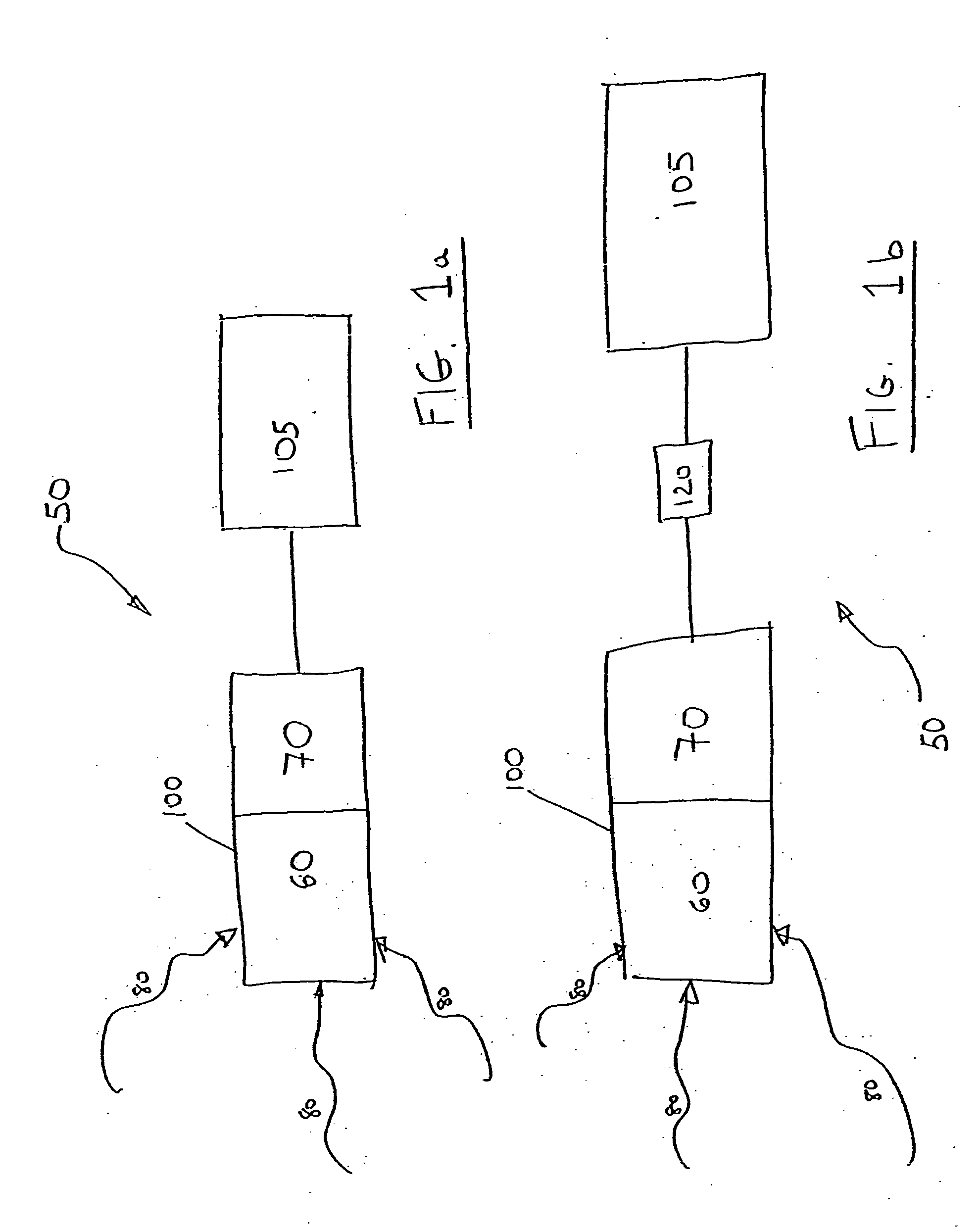
[0114] One aspect of the present invention is represented as a block diagram in FIG. 1a. In the internal power system 50, internal body tissue motion 80 is h...


PUM


Abstract

A micro-generator implant device including (a) a micro-generator, disposed within a living body, the micro-generator including: (i) a first mechanism for harnessing mechanical energy from a natural body movement, and (ii) a second mechanism for converting the mechanical energy to electrical energy, the electrical energy for providing power within the living body.

Description

FIELD AND BACKGROUND OF THE INVENTION [0001] The present invention relates to an Internal Energy Source (IES) for powering an implant or an energy storage unit thereof and in particular, to a micro-generator implant for providing power within a living body. [0002] Many implantable medical devices, such as pacemakers and defibrillators, require an electrical energy source. In pacemakers and defibrillators, this energy source normally is provided by a battery pack that is contained within the implanted device. Although rechargeable batteries have been successfully employed in a variety of applications, some present day pacemakers and defibrillators use non-rechargeable batteries. [0003] Surgery, with its attendant risks, discomforts, and cost is required when it becomes necessary to replace an implanted medical device. Because the batteries are hermetically sealed within the implanted device, the entire medical device must be surgically replaced if the batteries become depleted. To av...

Claims


Application Information

Patent Timeline
IPC IPC(8): A61N1/05A61N1/36A61N1/372A61N1/378
CPCA61N1/0587A61N1/37205H02K35/02H02K7/1823H02K7/1876A61N1/3785
Inventor HOLZER, ASHER
Owner SIRIUS IMPLANTABLE SYST
Why Eureka
Try Eureka