Heat exchanger for air and freezer device

a technology of air and freezer device and heat exchanger, which is applied in the field of air heat exchanger and refrigeration apparatus, can solve the problems of reducing refrigerating capacity, heat exchanger reducing evaporation performance and heating performance, and heat exchanger reducing heat exchange capacity, so as to suppress the reduction of energy efficiency, prevent the reduction of an effect of refrigerating operation, and reduce the effect of heating comfor

Inactive Publication Date: 2005-11-24
DAIKIN IND LTD
View PDF2 Cites 27 Cited by
  • Summary
  • Abstract
  • Description
  • Claims
  • Application Information

AI Technical Summary

Benefits of technology

[0084] The refrigeration apparatus with such a configuration is configured so that the fins of the evaporator have the surface structure as described above, and the blower is operated after interfacial frost or ice in contact with the surface portions A during defrost operation has melted, and thus can prevent reduction in an effect of refrigerating operation (e.g. reduction in heating comfort when the apparatus is applied to a heat pump air conditioner) and suppress reduction in energy efficiency as in the above-described refrigeration apparatus.
[0085] Since the refrigeration apparatus activates the defrost cycle and stops the blower until interfacial frost or ice in contact with the surface portions A melts during defrost operation, the blower blows wind only when frost or ice attached to the heat exchange surface is intended to be blown off by the wind pressure, and can further improve energy efficiency as compared with the above-described first solution means.
[0086] Further, the refrigeration apparatus of the present invention may be configured as a heat pump refrigeration apparatus which can be operated for heating and cooling, so that the apparatus comprises an evaporator consisting of the air heat exchanger having the above-described fin surface structure; a blower for blowing air to be heat-exchanged with the evaporator across the evaporator; a refrigerant circuit that can be operated in a defrost cycle in which a gas discharged from a compressor is supplied to the evaporator during defrost operation; and a control unit for controlling the apparatus to activate

Problems solved by technology

When frost is produced, the air heat exchanger exhibits reduced heat exchange capacity, thereby reducing refrigerating capacity.
In addition, the outdoor heat exchanger has reduced evaporation performance and heating performance when frosted.
Thus, defrost operation is appropriately carried out in order to remove the attached frost or ice as frozen frost (hereinafter simply referred to as frost or ice) However, when the defrost operation is carried out, the heating operation may halt or the heating capacity may be reduced, depending on the method of the defrost operation, and thus the heating comfort is disadvantageously reduced.
However, it has been found that the above conventional paints have a PTFE powder only poorly dispersed uniformly in the resin, have a poorly water-repellent area remaining on the surface, and exhibit an impaired antifrosting effect.
In addition, since it is difficult to avoid

Method used


Image

  • Heat exchanger for air and freezer device
  • Heat exchanger for air and freezer device
  • Heat exchanger for air and freezer device

Examples


embodiment 1

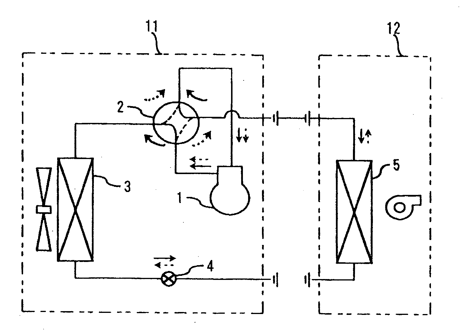
[0509] Embodiment 1 will be described with reference to FIGS. 29 and 30. FIG. 29 is a view showing a refrigerant circuit of the refrigeration apparatus of Embodiment 1. FIG. 30 is a perspective view showing an outdoor heat exchanger used in the same refrigeration apparatus.

[0510] The refrigeration apparatus of Embodiment 1 is a separate heat pump air conditioner, as shown in FIG. 29. The discharge side and the suction side of a compressor 1 are connected to a discharge port 2a and a suction port 2b of a four-way selector valve 2. Between switching ports 2c and 2d of the four-way selector valve 2, an outdoor heat exchanger 3, an expansion mechanism 4, and an indoor heat exchanger 5 are connected to each other. The compressor 1, the four-way selector valve 2, and the outdoor heat exchanger 3 are stored in an outdoor unit 11, and the indoor heat exchanger 5 is stored in an indoor unit 12. By switching the four-way selector valve 2, during cooling, a refrigerant is caused to flow as in...

embodiment 2

[0518] Embodiment 2 is a refrigeration apparatus using slit plate fins (slit fins) 21 instead of the flat plate fins 15 in Embodiment 1. FIG. 31 is a cross-sectional view of an outdoor heat exchanger 3 of the refrigeration apparatus of this Embodiment 2 cut with the cross-section of slit plate fins 21. FIG. 32 is a cross-sectional view of an outdoor heat exchanger 3 of the refrigeration apparatus of Embodiment 2 cut with the plane of a slit plate fin 21. FIG. 32 shows only the slit plate fin 21 for one row of heat exchange pipes 22.

[0519] As shown in the figures, in the slit plate fins 21 of the outdoor heat exchanger 3 in this embodiment, large or small trapezoid slits 21a and 21b are formed between the adjacent heat exchange pipes 22.

[0520] According to the refrigeration apparatus of this Embodiment 2, since the heat exchange surface of the outdoor heat exchanger 3 has the same surface structure as in Embodiment 1, the embodiment can exhibit the same effect as in Embodiment 1.

[...

embodiment 3

[0522] Embodiment 3 is a refrigeration apparatus using louver plate fins (louver fins) 31 instead of the flat plate fins 15 in Embodiment 1. FIG. 33 is a cross-sectional view of an outdoor heat exchanger 3 of the refrigeration apparatus of this Embodiment 3 cut with the cross-section of louver plate fins 31.

[0523] As shown in the figure, in the louver plate fins 31 of the outdoor heat exchanger 3 in this embodiment, louvers 31a are formed at a predetermined pitch.

[0524] Because of this, according to the refrigeration apparatus of this Embodiment 3, since the heat exchange surface of the outdoor heat exchanger 3 has the same surface structure as in Embodiment 1, the embodiment can exhibit the same effect as in Embodiment 1.

[0525] Since the refrigeration apparatus of this Embodiment 3 uses the louver plate fins 31, frost or ice can be easily cut with the louvers 31a during defrost operation. Thus, a mass of frost or ice attached to the heat exchange surface can be made suitably sma...


PUM

PropertyMeasurementUnit
Temperatureaaaaaaaaaa
Fractionaaaaaaaaaa
Percent by massaaaaaaaaaa

Abstract

Surface portions A with a low heat capacity and surface portions B to which frost or ice is poorly bound or attached are discretely distributed on the heat exchange surface. The surface portions A and the surface portions B have features by which, when heating the heat exchanger to which frost or ice is attached, frost or ice in contact with the surface portions A melts earlier than frost or ice in contact with the surface portions B, and at least a part of frost or ice attached to the surface portions B is made partially continuous with at least a part of frost or ice attached to the surface portions A and is thereby released from the surface portions B by its own weight. The heat exchanger having such a heat exchange surface is used as an evaporator of a refrigeration apparatus.

Description

TECHNICAL FIELD [0001] The present invention relates to an air heat exchanger and a refrigeration apparatus, in particular, to a heat exchanger with an improved surface structure. BACKGROUND ART [0002] Generally, in a refrigeration apparatus using an air heat exchanger as an evaporator, when air to be heat-exchanged with the air heat exchanger has a low temperature, and the evaporator has a low evaporation temperature, frost is produced on the heat exchange surface. When frost is produced, the air heat exchanger exhibits reduced heat exchange capacity, thereby reducing refrigerating capacity. [0003] For example, in a heat pump air conditioner as a refrigeration apparatus, when the outside air temperature is lowered during heating operation, the evaporation temperature is lowered, and an outdoor heat exchanger using an air heat exchanger is frosted. In addition, the outdoor heat exchanger has reduced evaporation performance and heating performance when frosted. Thus, defrost operatio...

Claims


Application Information

Patent Timeline
IPC IPC(8): C09D7/62C09K5/00F28F13/18F28F19/00
CPCB82Y30/00C08K3/04C09D7/1216F28F19/006C09K5/00F28F13/185C09D7/1291C09D7/70C09D7/62
Inventor YOSHIOKA, SHUNKASAI, KAZUSHIGEKOBAYASHI, SHINICHIROUNAKATA, HARUO
Owner DAIKIN IND LTD
Why Eureka
Try Eureka