Coil arrangement and method for its manufacture

a technology of coil arrangement and coil structure, which is applied in the direction of transformer/inductance magnetic core, inductance, and magnetic core manufacturing, etc., can solve the problems of increasing the number of coils, etc., to achieve the effect of reducing external leakage fields, simple, compact, and material-saving coil arrangement construction

Inactive Publication Date: 2005-11-24
MINEBEA CO LTD
View PDF4 Cites 19 Cited by
  • Summary
  • Abstract
  • Description
  • Claims
  • Application Information

AI Technical Summary

Benefits of technology

[0008] The invention goes to produce a coil arrangement which is perfectly suited for use as either a choke or a transformer in high-frequency applications. For example, the coil arrangement can be used as a storage choke in a switch mode power supply. The coil arrangement according to the invention makes it possible to achieve excellent characteristics in terms of power density, efficiency and electromagnetic induction. There is the additional advantage that the coil arrangement according to the invention is very compact and flat, making the coil arrangement perfectly suited for SMD (Surface Mounted Device) technology on circuit boards.
[0029] Particularly in the case of large coil arrangements and small spacings between the cores, it is advantageous if the legs of two cores located opposite each other are additionally secured, for example, by adding a drop of epoxy resin.

Problems solved by technology

The resulting multi-layer windings, however, create considerable losses through skin effect or proximity effect.
Inherent to this technology, however, are winding geometries whose magnetic fields have an impact well beyond the immediate vicinity of the component.
This detrimental characteristic is particularly evident in the case of magnetic components that have low relative effective magnetic permeability (e.g. storage coils) and results in undesirable induction effects on adjoining circuit components and in additional power dissipation.

Method used


Image

  • Coil arrangement and method for its manufacture
  • Coil arrangement and method for its manufacture
  • Coil arrangement and method for its manufacture

Examples


Embodiment Construction

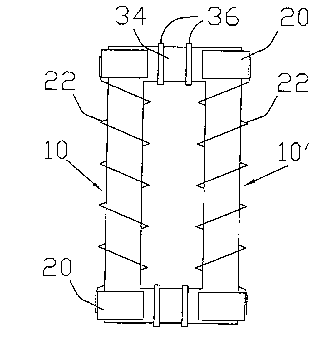
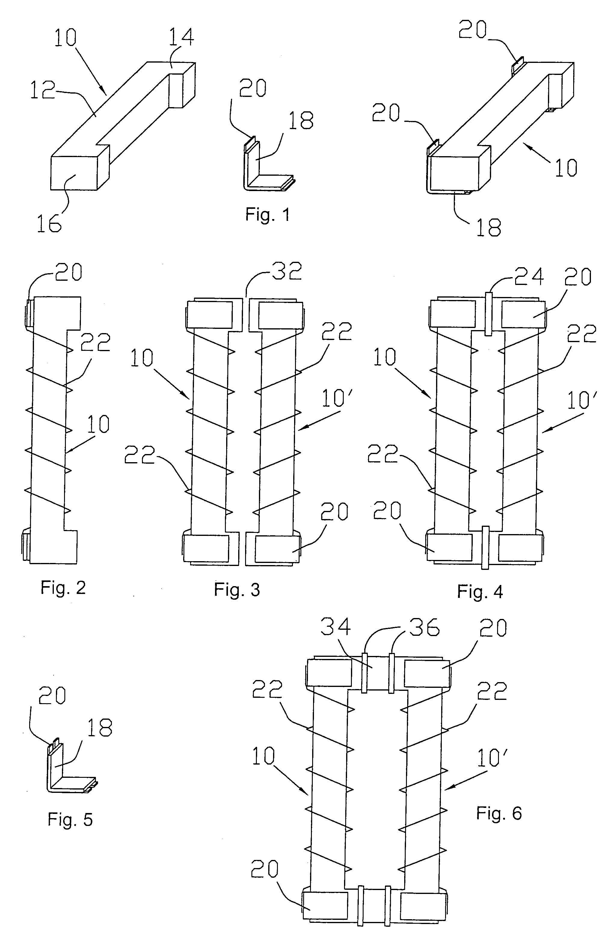
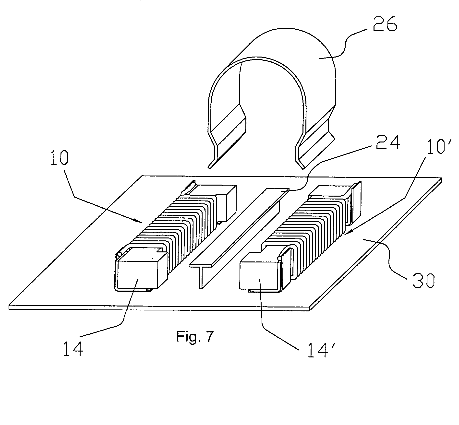
[0038] The coil arrangement according to the invention is based on the use of two identical C-shaped cores, or C-cores, each forming one half of the coil. The C-cores are preferably made from a ferrite material. FIG. 1 shows a perspective view of a C-core 10 which has an elongated base 12 and two comparatively short legs 14, 16 protruding from the ends of the base and perpendicular to the base. The C-core of the coil arrangement according to the invention is preferably designed with relatively short legs 14, 16 that project from the base 12 by slightly more than a winding diameter. The C-core 10 thus degenerates towards an I-core. The illustrated C-core 10 structure means that only minimum space is required for the construction of the coil arrangement according to the invention.

[0039] The base 12 is preferably coated with an insulating material, e.g. with an insulating plastic tape or a coat of epoxy. This makes it possible to mount a winding directly onto the core 10 without the n...


PUM

PropertyMeasurementUnit
frequencyaaaaaaaaaa
temperaturesaaaaaaaaaa
insulatingaaaaaaaaaa

Abstract

A coil arrangement that has a primary and a secondary C-shaped core, each C-shaped core having an elongated base and two shorter legs at the ends of the base, a winding being applied to each base and the ends of the windings being electrically connected at the legs of the cores and the cores being arranged with respect to each other such that the legs of the two cores are located opposite each other.

Description

FIELD OF THE INVENTION [0001] The invention relates to a coil arrangement and a method for its manufacture. The invention particularly relates to a coil arrangement that can be employed in high-frequency applications as a choke, a storage choke for example, or as a high-frequency transformer. One practical application of the coil arrangement according to the invention is its use in a switch mode power supply. BACKGROUND OF THE INVENTION [0002] A coil arrangement that can be employed as a power transformer in a switch mode power supply is described, for example, in U.S. Pat. No. 5,543,773. The coil arrangement revealed in this document uses a primary and a secondary winding which are mounted onto a trapezoid core and interleaved on the same winding layer. The aim of this arrangement is to minimize the leakage flux density and thus to minimize losses of the coil arrangement, and, more generally, to minimize winding conduction losses. To this effect, a relatively complex, interleaved w...

Claims


Application Information

Patent Timeline
Patent Type & Authority Applications(United States)
IPC IPC(8): H01F27/28H01F17/04H01F27/24H01F27/29H01F37/00H01F41/00H01F41/02
CPCH01F17/045H01F41/0206H01F27/292
Inventor WEGER, ROBERT
Owner MINEBEA CO LTD
Why Eureka
Try Eureka