Metal plate resistor

a technology of metal plate and resistor, which is applied in the direction of resistors, resistor details, adjustable resistors, etc., can solve the problems of deterioration of soldered joints between aluminum mounting boards and metal plate resistors, and achieve the effect of high stability against aging

Active Publication Date: 2005-11-24
KOA CORP
View PDF15 Cites 37 Cited by
  • Summary
  • Abstract
  • Description
  • Claims
  • Application Information

AI Technical Summary

Benefits of technology

[0006] It is therefore an object of the present invention to provide a metal plate resistor which is of a small-size compact structure, and which is highly stable against aging and environmental changes due to mechanical, thermal, and electrical stresses after it is mounted on a mounting board such as an aluminum mounting board even though the difference of coefficients of thermal expansion between the mounting board and the metal plate resistor exists.

Problems solved by technology

Since an aluminum mounting board and a metal plate resistor mounted thereon have largely different coefficients of thermal expansion, the soldered joint between the aluminum mounting board and the metal plate resistor tends to be deteriorated soon due to thermal fatigue.

Method used


Image

  • Metal plate resistor
  • Metal plate resistor
  • Metal plate resistor

Examples


first embodiment

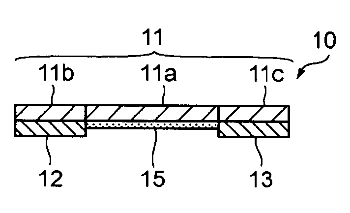
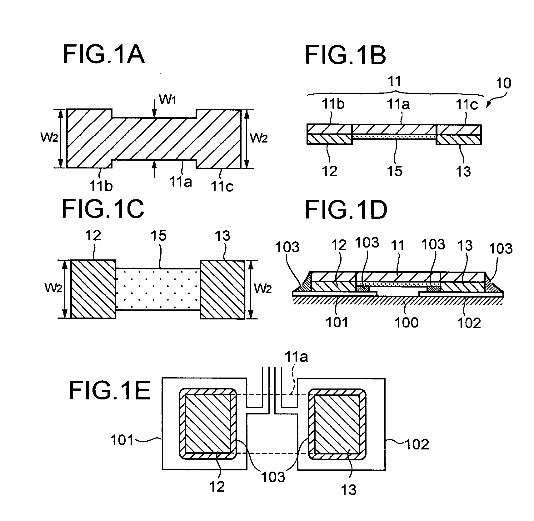
[0043]FIGS. 1A through 1E show a metal plate resistor 10 according to the present invention. The metal plate resistor 10 comprises a resistive body 11 in the form of a metal plate, a pair of electrodes 12, 13 in the form of thin plates of Cu (highly conductive metal conductor) joined respectively to the lower surfaces of opposite ends 11b, 11c of the resistive body 11. The resistive body 11 is made of a Cu—Ni alloy, a Ni—Cr alloy, a Fe—Cr alloy, a Pd—Pt alloy, an Au—Ag alloy, an Au—Pt—Ag alloy, or the like. The electrodes 12, 13 have molten solder layers or plated coating layers provided on their respective surfaces for allowing the electrodes 12, 13 to be easily soldered to a land pattern on a mounting board when the metal plate resistor 10 is mounted on the mounting board. An insulating layer 15 is disposed on the bottom surface of the resistive body 11 between the electrodes 12, 13 in covering relation to the bottom or reverse surface of the resistive body 11.

[0044] The metal pla...

fourth embodiment

[0054]FIGS. 6A and 6B show in perspective a metal plate resistor 20 according to the present invention. FIG. 6A shows a resistive body and electrodes of the metal plate resistor, and FIG. 6B shows the metal plate resistor as it is finished into a complete product with a protective coating on the resistive body and a plated coating on the electrodes. As shown in FIG. 6A, the metal plate resistor 20 comprises a resistive body 21 in the form of a metal plate (resistive alloy plate) made of a copper-nickel alloy, a nickel-chromium alloy, or the like, and a pair of electrodes 22 made of copper (highly conductive metal conductor) joined respectively to the lower surfaces of opposite ends of the resistive body 21.

[0055] The resistive body 21 has an H shape or butterfly shape as viewed in plan comprising a main section 21a positioned between the electrodes 22, 22 and a pair of electrode sections 21b, 21b including portions progressively wider than the main section 21a in directions away fro...


PUM


Abstract

A metal plate resistor includes a resistive body comprising a metal plate, and at least a pair of electrodes joined respectively to opposite ends of the resistive body, the electrodes being made of a highly conductive metal conductor. The resistive body has a main section positioned between the electrodes and a pair of electrode sections progressively wider than the main section in directions away from the main section. The electrodes are disposed respectively beneath the electrode sections and identical in shape to the electrode sections.

Description

BACKGROUND OF THE INVENTION [0001] 1. Field of the Invention [0002] The present invention relates to a metal plate resistor suitable for use in current detecting applications or the like. [0003] 2. Description of the Related Art [0004] Heretofore, metal plate resistors having a resistive body in the form of a metal plate with electrodes attached to its respective opposite ends have widely been used as current detecting resistors or the like. Known metal plate resistors are made of a copper-nickel alloy, a nichrome alloy, an iron-chromium alloy, a manganin alloy, or the like, and has a low resistance of several mΩ or lower. For details, reference should be made to Japanese laid-open patent publication No. 2002-184601. [0005] Some metal plate resistors for use in harsh environments at high temperatures, such as in automobiles, are mounted on aluminum mounting boards that have a good heat radiating capability and are of a relatively low cost. Since an aluminum mounting board and a meta...

Claims


Application Information

Patent Timeline
Patent Type & Authority Applications(United States)
IPC IPC(8): H01C1/012H01C1/144H01C1/148H01C7/06
CPCH01C1/144H01C7/06H01C1/148
Inventor ISHIDA, KAZUHIROCHIKU, SATOSHI
Owner KOA CORP
Why Eureka
Try Eureka