Electro-optical shutter

a shutter and optical technology, applied in the field of multimedia, can solve the problems of not being available on the same disc, the light-sampling system is the fixed sampling window, and the blurring effect is damaged, so as to reduce the range of motion, reduce the amount of time available for sampling, and diminish the effect of blurring

Inactive Publication Date: 2005-11-24
ROBERTSON JERRY LYNN +1
View PDF17 Cites 21 Cited by
  • Summary
  • Abstract
  • Description
  • Claims
  • Application Information

AI Technical Summary

Benefits of technology

[0014] The microprocessor in the electronic control circuit may execute a software algorithm to control the liquid crystal display element. The liquid crystal display element may be located between a lens and an image capture device. A user interface may be provided for selecting a shutter angle setting. The microprocessor may develop an electrical output signal based on the synchronization signal from the video camera and on one of a plurality of pre-programmed shutter angle settings that may be selected by a user. Within the video camera image sampling period, the electrical output signal from the programmable electronic control circuit may control the liquid crystal display element to adjust a time that the optical path is ‘open’, allowing light to reach the image capture device, and a time that the optical path is ‘closed’, blocking light from reaching the image capture device. Selectively reducing the amount of time available to sample the image by interrupting the optical path reduces the range of motion captured from an action scene. This shorter range of motion results in diminishment or elimination of the ‘motion blur’ effect, resulting in a clearer action sequence.
[0015] The electro-optical shutter can also be viewed as providing methods for reducing motion blur in action sequences recorded by video cameras. In this regard, one embodiment of such a method, among others, can be broadly summarized by the following steps: equipping a video camera with an electro-optical shutter; providing power to the camera and the electro-optical shutter; selecting one of a plurality of preprogrammed shutter angle settings; and operating the video camera to record the selected action sequence.

Problems solved by technology

The blurring effect is caused by the film movie camera capturing excessive movement of a subject due to the relatively long film exposure time compared to, for example, shorter film exposure time available on a still camera.
Reducing the film exposure time results in capturing less movement in an action sequence, thereby dampening the blurring effect.
A disadvantage of the mechanical light-sampling system is the fixed sampling window.
While other window sizes may be available (e.g., 90 degree windows), they may not be available on the same disc.
Because of the fixed sampling period of the digital video camera, often about thirty (30) samples-per-second, the amount of image information captured from an action sequence can result in the appearance of ‘motion blur’ when the action sequence is reproduced for a viewer.
Digital video cameras, however, feature small size and low power consumption.
Using a motor-driven disc in the optical path to eliminate motion blur effects would be unwieldy and inconvenient, and would unacceptably increase power consumption.
Thus, a heretofore unaddressed need exists in the industry to address the aforementioned deficiencies and inadequacies.

Method used


Image

  • Electro-optical shutter
  • Electro-optical shutter
  • Electro-optical shutter

Examples


Embodiment Construction

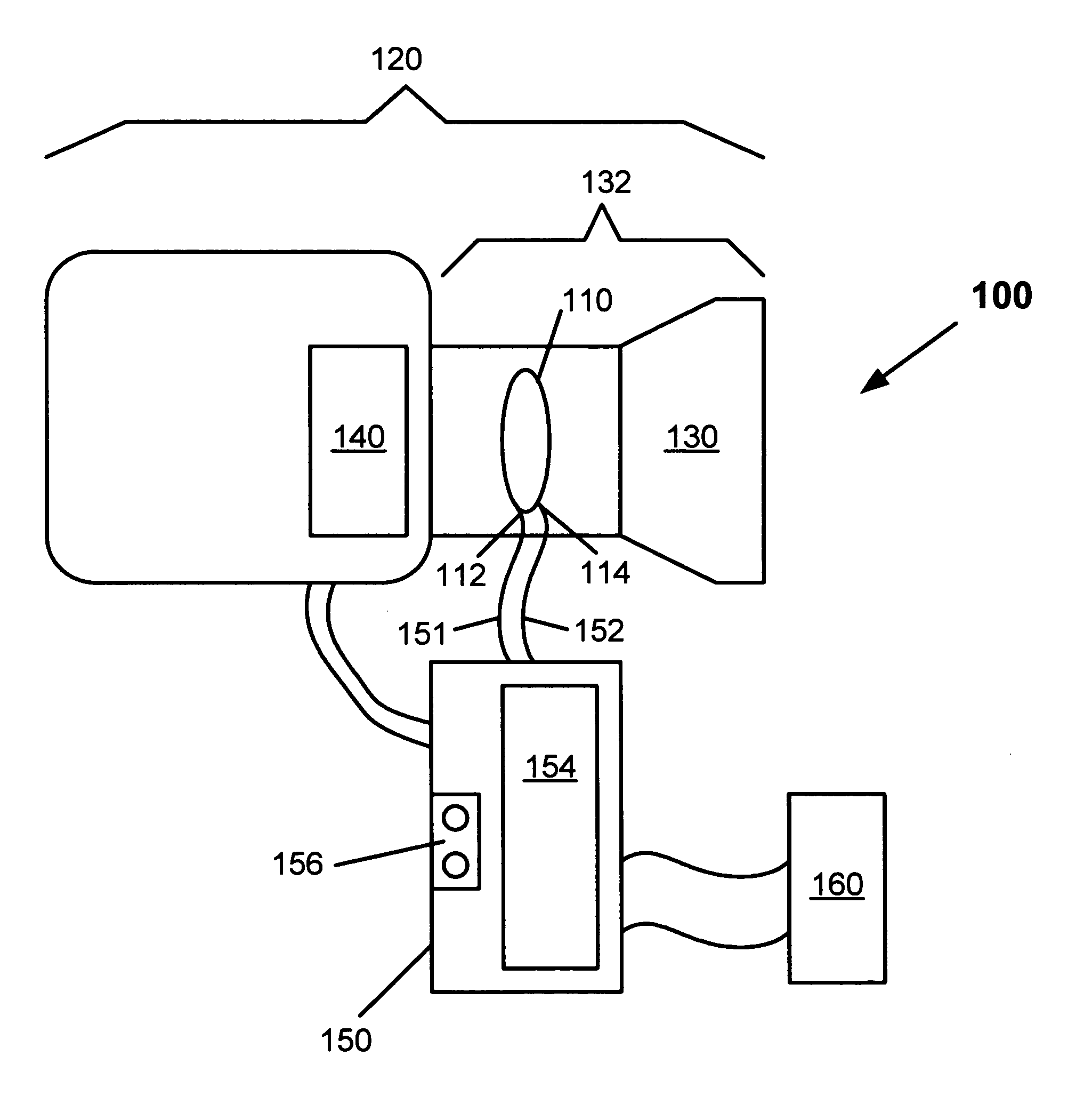
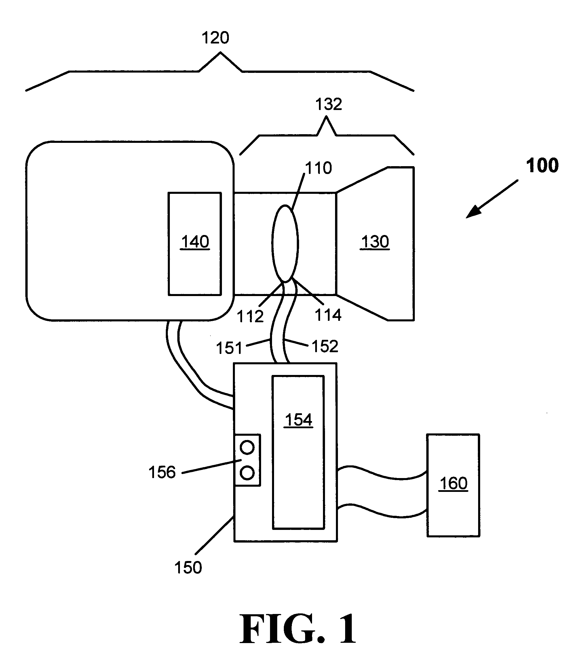
[0024] An electro-optical shutter is a small, lightweight, programmable apparatus that uses a liquid crystal element to optically deblur action sequences captured by a video camera. By synchronizing to a signal from a video sampling system of the video camera, the liquid crystal element precisely interrupts the optical path from a lens of the video camera to an image capture device within the video camera. As described here, a video camera may include any motion picture camera capable of capturing and processing images in an electronic format, as an example, but not limited to, a digital video (DV) camera, which uses an electronic image capture device, such as, but not limited to, at least one charge coupled device.

[0025]FIG. 1 is a block diagram illustrating the major elements of a first exemplary embodiment of an electro-optical shutter apparatus. The electro-optical shutter apparatus 100 comprises a liquid crystal display (LCD) element 110 disposed in an optical path 132 of a vi...


PUM


Abstract

An electro-optical shutter apparatus provides optical deblurring of images captured with a video camera. A liquid crystal element in the optical path of a video camera selectively interrupts the optical path of the video camera. An electronic circuit contains a microprocessor that executes a software algorithm to control the liquid crystal element and synchronize its operation to the video camera. Based on input from the user, the liquid crystal element opens and closes at the appropriate times to reduce the time available for the video camera to sample the desired image. When capturing an action sequence, therefore, the camera captures less motion of the subject during each sampling period, resulting in decreased motion blur.

Description

FIELD OF TECHNOLOGY [0001] The present invention is generally related to multimedia, and more particularly is related to an apparatus for deblurring action sequence images during acquisition with a digital video camera. BACKGROUND [0002] During filming of a movie with a film movie camera, an image is captured on each frame of a film with an ‘open shutter.’ The result of a long ‘open shutter’ film exposure can be blurring of a captured image, known as a blurring effect. When a viewer sees the film, the visual cortex of the brain of the viewer attempts to correct the blurring effect by comparing the image to what the viewer sees in everyday life. The blurring effect is caused by the film movie camera capturing excessive movement of a subject due to the relatively long film exposure time compared to, for example, shorter film exposure time available on a still camera. The relatively long exposure time is the result of a fixed open shutter setting. [0003] In a modern motion picture film...

Claims


Application Information

Patent Timeline
Patent Type & Authority Applications(United States)
IPC IPC(8): H04N5/225H04N5/235H04N5/238
CPCH04N5/2254H04N5/238H04N5/2353H04N23/55H04N23/75H04N23/73
Inventor ROBERTSON, JERRY LYNNROBERTSON, CHARLES MACIAN
Owner ROBERTSON JERRY LYNN
Why Eureka
Try Eureka