Spray controlled cleaning brush apparatus and method for use

a technology of cleaning brush and controlled spray, which is applied in the direction of brushes, household cleaners, tableware washing/rinsing machines, etc., can solve the problems of insufficient amount of liquid, time-consuming and cumbersome standard cleaning methods utilizing any of the above and other methods, and would require an extra amount of time to towel dry, so as to facilitate operation, reduce the complication of dumping, and simple structure

Inactive Publication Date: 2005-11-24
HAPPY LIFE HOME PROD
View PDF9 Cites 17 Cited by
  • Summary
  • Abstract
  • Description
  • Claims
  • Application Information

AI Technical Summary

Benefits of technology

[0018] In comparison to the existing technologies, the uniqueness of this invention is set forth as the followings: (1) The handle is converted into liquid chamber and carries liquid supplied the user with the necessary liquid for cleaning thus avoiding the trouble of alternating the spraying of the cleaning and brushing the objects and the two missions of spraying and brushing can be combined into one ongoing and fluid motion or movement. The spraying pump is used to prevent the detergent, despite of the texture, in the liquid chamber from leaking; (2) Minimize the complication of dumping out and losing detergent while cleaning the cleaning brush; (3) Directly control the amount of detergent through the pressing button to facilitate the operation; (4) The invented pump body, which eliminates a one-direction-only valve, has a simple structure; the other end of the body pump is well sealed by the installing stand; (5) This invented product can spray in all directions and is controlled by a pump that will prevent the uncontrolled leakage of liquid to the outside of the chamber regardless of the thickness of the liquid; (6) By the use of a pump as opposed to other inventions whereby the amount of liquid is controlled by the height of the liquid reservoir raised above the brush whereby only gravity is used to control the amount of fluid that is emitted, and by using the pump the user can control the quantity of the liquid used thereby eliminating overspill of liquid and waste; (7) The pump mechanism within the body uses only 1 valve instead of 2 and is a simpler structure than most other pump mechanisms thereby minimizing malfunction; (8) This invention can be used to spray in all directions by pointing the tip of the apparatus in the direction of the desired location and pressing the pump.

Problems solved by technology

The standard method of cleaning utilizing any of the above and other methods tends to be time consuming and cumbersome.
Along with the need to constantly rewet the area to be cleaned, comes also the requirement for the user to dry such area to be cleaned of such liquids and cleansers due to the imprecise measurement of liquid required for the individual cleaning job as either an insufficient amount or is usually the case an excess of such liquid is released onto the surface to be cleaned or surrounding areas.
Typically, the amount of liquid is in excess and would require an extra amount of time to towel dry, with repeated wringing of the towel or with excess waste of paper towels.

Method used


Image

  • Spray controlled cleaning brush apparatus and method for use
  • Spray controlled cleaning brush apparatus and method for use
  • Spray controlled cleaning brush apparatus and method for use

Examples


Embodiment Construction

[0029] Detailed descriptions of the preferred embodiment are provided herein. It is to be understood, however, that the present invention may be embodied in various forms. Therefore, specific details disclosed herein are not to be interpreted as limiting, but rather as a basis for the claims and as a representative basis for teaching one skilled in the art to employ the present invention in virtually any appropriately detailed system, structure or manner. Referring to the drawing figures, like reference numerals designate identical or corresponding elements throughout the several figures.

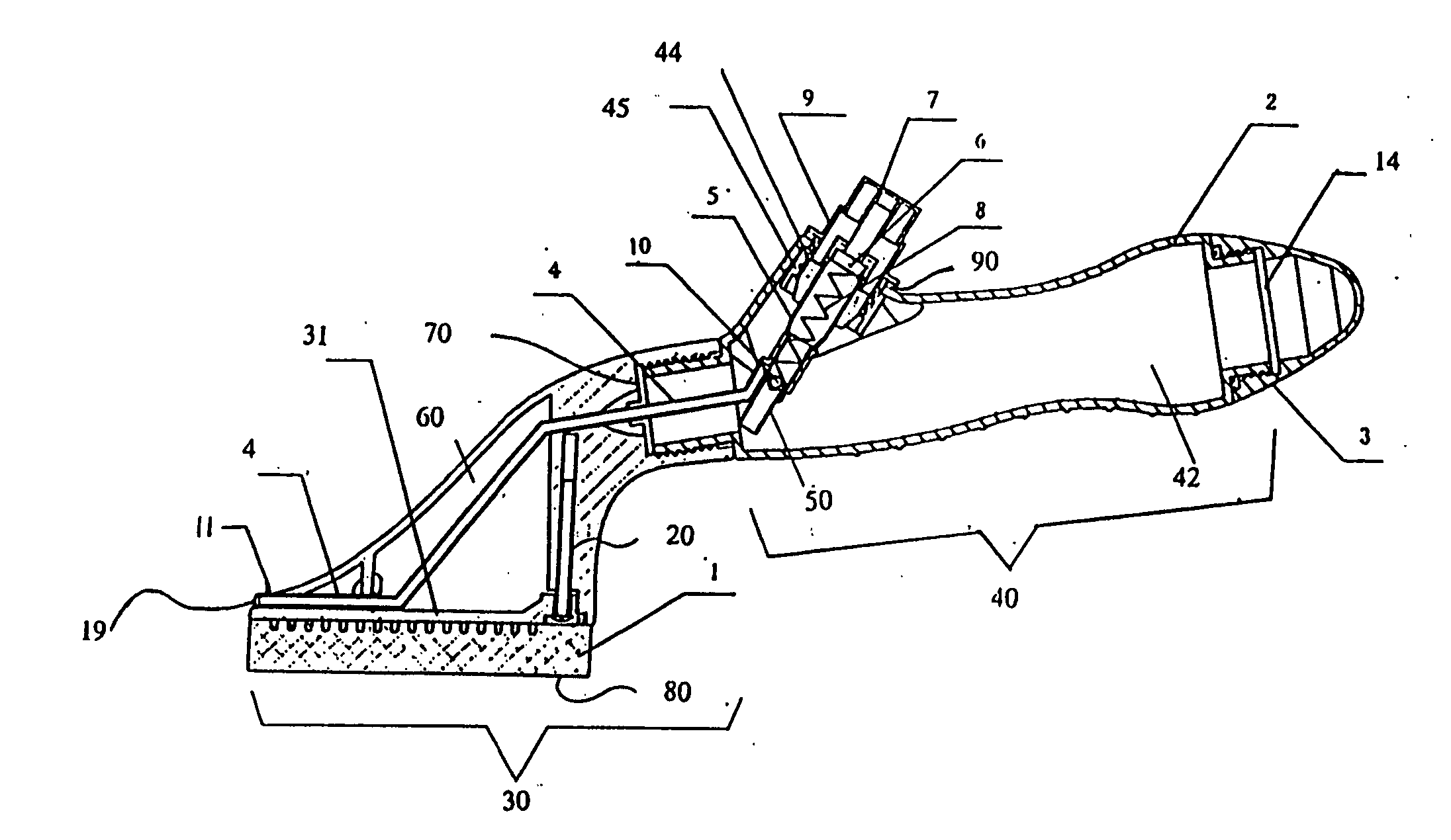
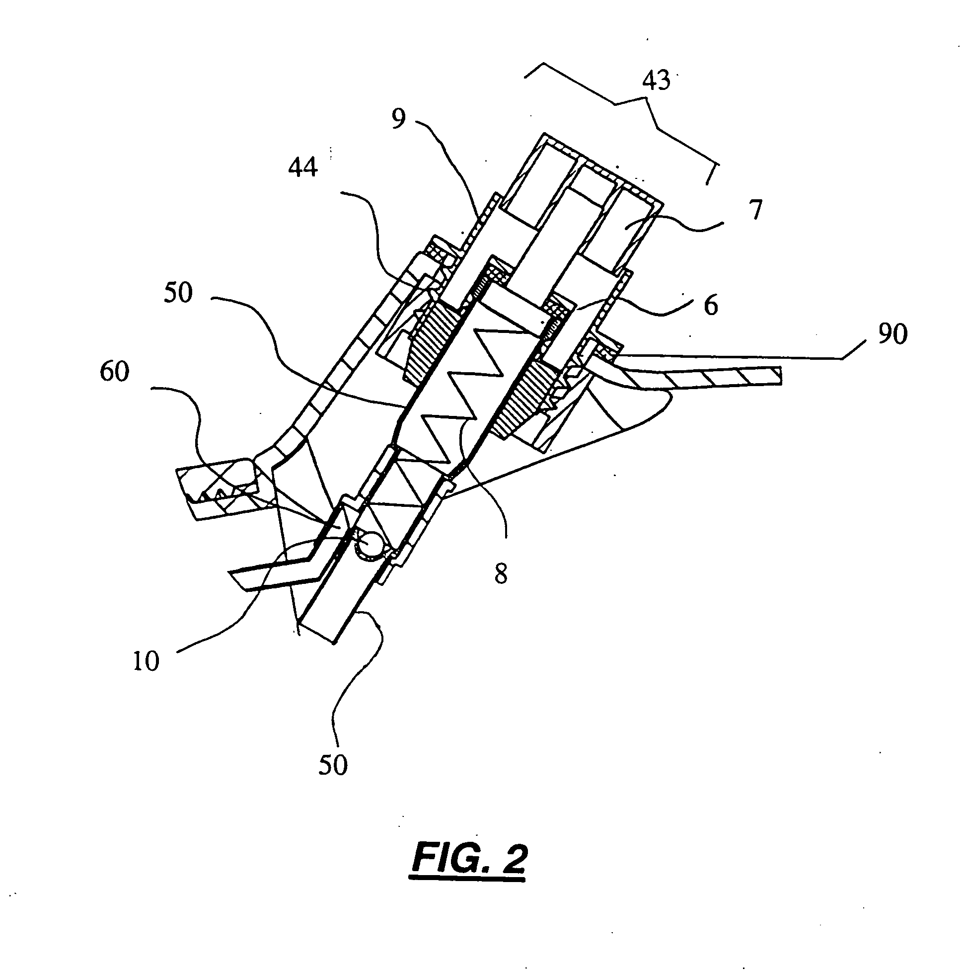
[0030] In accordance with a preferred embodiment of the invention, there is disclosed Spray Controlled Cleaning Brush and Liquid Reservoir comprising: a cleaning brush head and attachment means for securely attaching a reservoir handle, an end cap for sealing liquid within said reservoir handle, a spray assembly enclosed within the body of the reservoir handle, a straw acting as a liquid dispensing...


PUM


Abstract

A Spray Controlled Cleaning Apparatus provides a means for users of the spray controlled cleaning brush to clean and brush with a cleanser liquid without the need to carry another container for the liquid cleanser. The present invention combines the advantages of having an easy to use cleaning brush with a reservoir capable of holding the appropriate cleaning cleanser solvent for the particular cleaning task, and having the advantage of liquid ejection in a controlled spray pattern and amount desired. The operation of the spaying pump body is accomplished by pressing the pressing button, the pressure increases, the liquid within the pump body, which was pressured by the piston, is prevented from entering into sucking head by the one-direction-only valve and is sprayed out through the spraying head of the pump body. By releasing the pressing button, the piston returns to its original position under the effect of the spring. The pressure of the liquid within the pump body decreases. Under the negative pressure, the one-direction-only valve within the sucking head departs from sucking head, the liquid then is sucked into the pump body. The pathway of the one-direction-only valve of the spraying head is blocked. Repeating the same procedures will cause liquid to be sprayed to an object repeatedly and continuously. The amount of cleanser, detergent or other liquid is controlled by the number of times the pressing button is depressed. As the pressing button is released, the gasket seal cap slit is closed and no seepage of cleanser occurs. The brush head portion is interchangeable from bristles, to sponge, scouring pad, or any combination thereof by way of a screw.

Description

BACKGROUND OF THE INVENTION [0001] 1. Field of the Invention [0002] The present invention generally relates to the field of cleaning brushes and more specifically to a controlled cleanser spraying cleaning brush with an attached cleanser reservoir in the attached brush handle. [0003] 2. Brief Description of the Related Art [0004] Originally, cleaning brushes were made and used for cleaning any items in the home including the kitchen, bathrooms, stoves, appliances, dishes, cups and used in cooking for cleaning fruits and vegetables. Industrial uses involving and requiring cleaning require brushes to remove dirts or unwanted soiled matter from many articles on the surface or on the interior. Cleaning brushes are one of the most frequently used cleaning tools in existence today. Mostly brushes have heads which are made of sponge or fiber materials or bristles. When one uses a traditional cleaning brush one usually has to hold a brush and a spray detergent side by side or spray the dete...

Claims


Application Information

Patent Timeline
Patent Type & Authority Applications(United States)
IPC IPC(8): A46B11/00A46B11/02A47L15/00B43K5/02
CPCA46B11/0058
Inventor GU, HUI
Owner HAPPY LIFE HOME PROD
Why Eureka
Try Eureka