I/Q compensation of frequency dependent response mismatch in a pair of analog low-pass filters

a low-pass filter and frequency-dependent technology, applied in the field of compensation of matched twopath real filter pairs, can solve the problems of significant complicating the modeling and compensation, affecting the performance of direct conversion receivers, transmitters, transceivers,

Inactive Publication Date: 2005-11-24
AVAGO TECH INT SALES PTE LTD
View PDF9 Cites 89 Cited by
  • Summary
  • Abstract
  • Description
  • Claims
  • Application Information

AI Technical Summary

Benefits of technology

[0040] In some embodiments in accordance with the invention, e.g., using transceivers, various components already available may be reused for the test signal generation, measurement, and/or determination. For example, when performing operations related to the compensation of the transmitter's LPFs, the receiver's ADCs may coupled to the output of the transmitter's LPFs. The ADCs may be coupled to an existing DSP....

Problems solved by technology

Unfortunately, the characteristics of direct conversion receivers, transmitters, and transceivers are not ideal.
Even when the filters are fabricated at the same time and on the same integrated chip, component mismatch of 0.2% to 0.5% or even larger may still occur.
Note that the LPF error model representation coefficients are a function of frequency, which significantly complicates the modeling and compensation.
Thus, the implementation of the correction matrix Acorr (ω) becomes costly since it should be effective over the whole band of frequencies of interest.
The incorporation of elaborate testing circuitry and elaborate correction circuitry (e.g., sometimes including 1,000 to 100,000 or more gates) may consume significant power, may occupy a significant amount of limited circuit board space available, and may add significant cost to the device.
In many low cost, limited power, miniature size applicati...

Method used


Image

  • I/Q compensation of frequency dependent response mismatch in a pair of analog low-pass filters
  • I/Q compensation of frequency dependent response mismatch in a pair of analog low-pass filters
  • I/Q compensation of frequency dependent response mismatch in a pair of analog low-pass filters

Examples


Embodiment Construction

[0061] The present invention involves novel methods and apparatus for compensating frequency dependent mismatch such as frequency dependent mismatch in a pair of analog real low pass filters. The following description is presented to enable one skilled in the art to make and use the invention, and is provided in the context of particular embodiments and methods. Various modifications to the disclosed embodiments and methods will be apparent to those skilled in the art, and the general principles set forth below may be applied to other embodiments, methods and applications. Thus, the present invention is not intended to be limited to the embodiments and methods shown and the inventors regard their invention as the following disclosed methods, apparatus and materials and any other patentable subject matter to the extent that they are patentable.

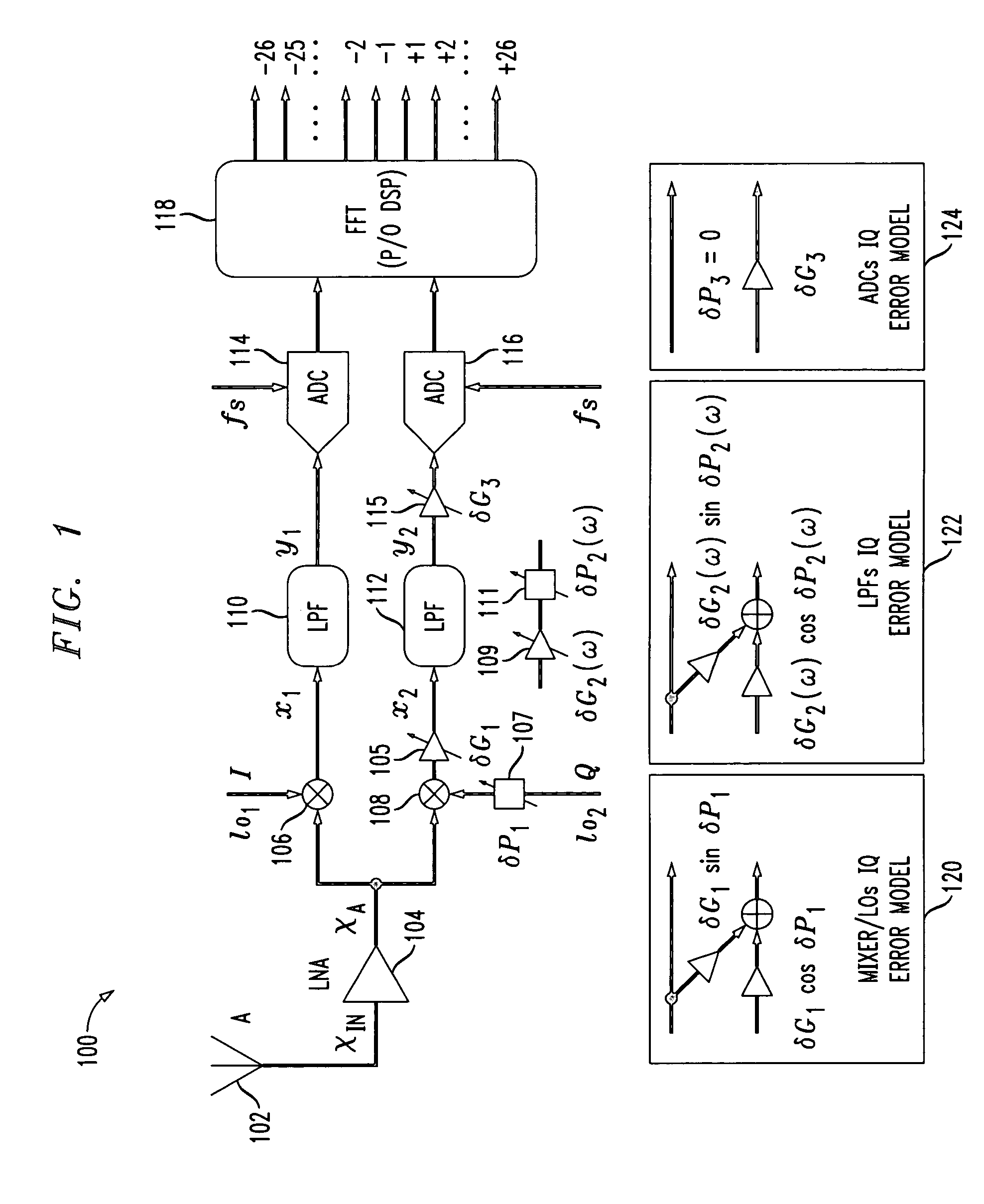
[0062]FIG. 5 illustrates an exemplary I / Q receiver chain 500 implemented in accordance with the present invention. Receiver chain 500 include...


PUM


Abstract

Frequency dependent I/Q imbalance in real I/Q filter pairs compensation may be performed using a simple compensation module, placed in the receiver/transmitter chain, with a gain adjustment coefficient and a delay adjustment coefficient. The gain adjustment coefficient may be determined by amplitude measurements conducted at a selected frequency near the center of the band-pass region of the filters. The delay adjustment coefficient may be determined by phase measurements conducted at a selected frequency near the edge of the band-pass region of the filters. Statistical analysis may be used to determine types of real filters that are better suited for the compensation method and to select the test frequencies that should be used.

Description

FIELD OF THE INVENTION [0001] The present invention concerns compensation of matched two-path real filter pairs. More specifically, the present invention concerns (I / Q) compensation of frequency dependent response mismatch for a pair of analog (low) pass filters. BACKGROUND [0002] Multiple channels of data can share a single transmission medium, but a receiver may desire data from one channel. Therefore, to isolate the desired channel for processing, transceivers typically perform at least three operations on the received signal: (1) the undesired channels are filtered out; (2) the desired channel is “shifted” to dc, where it can be processed; and (3) the signal is amplified. The order of the operations depends on the design of the transceiver. Shifting a signal may be accomplished by mixing the signal with a local oscillator signal. [0003] In superheterodyne transceivers, the input signal (e.g., a Radio Frequency (“RF”) signal) is amplified and filtered. Then, the filtered RF signa...

Claims


Application Information

Patent Timeline
IPC IPC(8): H04B17/00H04Q7/20
CPCH04B17/21
Inventor KISS, PETERPRODANOV, VLADIMIR
Owner AVAGO TECH INT SALES PTE LTD
Why Eureka
Try Eureka