Intramedullary pin tracking

a technology for intramedullary pins and tracking devices, applied in the field of intramedullary pin tracking devices, can solve the problems of inability to achieve the effect of reducing radiation load, reducing time and effort, and reducing radiation load

Active Publication Date: 2005-11-24
BRAINLAB
View PDF9 Cites 35 Cited by
  • Summary
  • Abstract
  • Description
  • Claims
  • Application Information

AI Technical Summary

Benefits of technology

[0011] The present invention provides a method, apparatus and system that detects and compensates for deformation in the intramedullary pin as it is inserted into the bone. More particularly, the present invention detects the deformation in the intramedullary pin and provides the information to a medical navigation system or the like. The deformation can be detected by a deformation detection device that extends along the intramedullary pin, wherein the deformation detection device communicates the deformation to the navigation system. An advantage of the present invention is that it provides precise navigation, while minimizing the invasive experience of the patient.
[0012] In practice, information on the position of the distal end of the intramedullary pin is composed of two pieces of information; an absolute position of the proximal end (via a reference device) of the intramedullary pin and information on the deformation, i.e., information relative to the non-deformed pin. The present invention enables one to deviate from the principle that previously had been used in both optical and magnetic target finding methods, namely that of directly and absolutely determining the position and orientation of the distal end of the intramedullary pin or bore. Faults and imprecision, which can occur when making such direct determinations due to patient tissue around the outside of the intramedullary pin, can be overcome by the present invention. Further, determining the target trajectory of the through-bore in the intramedullary pin can be controlled without using radiation in any of the degrees of freedom (three dimensions), thereby reducing the radiation load to the patient and operating team. Additionally, in accordance with the present invention, reference clamps are not required, thereby reducing the time and effort typically required to arrange such clamps. Further, this results in a less invasive experience for the patient.
[0013] In accordance with a preferred embodiment, the deformation detection device detects bending (both angular and torsional) in the intramedullary pin. In particular, the deformation detection device can extend from substantially the proximal end to substantially the distal end of the intramedullary pin, preferably from the proximal to the distal determining means, in particular the fixing bore of the pin.
[0014] The deformation detection device can be advantageously situated in the interior of the intramedullary pin and can be a fiber optic structure, in particular a glass fiber optic structure, which detects deformations on the basis of differences in light transit times. The fiber optic structure can include a structure with sequentially arranged fiber optic loops. Alternatively or additionally, the fiber optic structure can include at least two loop structures orientated at an angle with respect to each other, in particular perpendicular to each other, in order to facilitate the determination of torsional bending.
[0015] In a tracking method in accordance with the invention for determining or tracking the spatial position of an intramedullary pin in image-guided surgery, a reference device can be arranged on the proximal end of the intramedullary pin and located using a medical navigation system. The orientation of the intramedullary pin from the proximal end then can be determined, wherein deformations of the intramedullary pin can be detected by the deformation detection device extending along the intramedullary pin and communicated to the navigation system. Using this information, the position of the intramedullary pin after deformation can be displayed in the navigation system and, with the aid of this information, detected bending (both angular and torsional) in the intramedullary pin can be used when calculating the orientation of the fixing bore at the distal end, thereby enabling a fixing screw to be precisely inserted into the fixing bore.
[0016] A number of different technologies are combined by the present invention, including:

Problems solved by technology

One problem with conventional intramedullary pins is that the implanted intramedullary pin is deformed by the shape of the long bone as the intramedullary pin is introduced into the bone.
A disadvantage of this conventional approach is that it exposes the patient and operating team to an undesirable radiation load.
A further disadvantage in using C-arcs is the lack of a third dimension.
On the basis of intra-operatively produced x-ray projections, even from a number of angles, a sufficient spatial orientation for reliably controlling the introduction of screws in all three dimensions and all degrees of freedom generally is lacking.
The light source, however, can be difficult to identify, resulting in inaccurate identification of the fixing bore location.
A drawback to these systems is that they can be costly and relatively susceptible to faults.
In these systems, experience has shown that solely tracking the pin, without taking into account the deformation, generally leads to incorrect bores, despite the use of fluoroscopy in combination with navigation.
Another disadvantage of these known methods is that they are based on the use of radiation (C-arc) for imaging, and the position of the through-bores in the image is determined manually and imprecisely (due to misinterpretation of the displayed projection, for example).

Method used


Image

  • Intramedullary pin tracking
  • Intramedullary pin tracking
  • Intramedullary pin tracking

Examples


Embodiment Construction

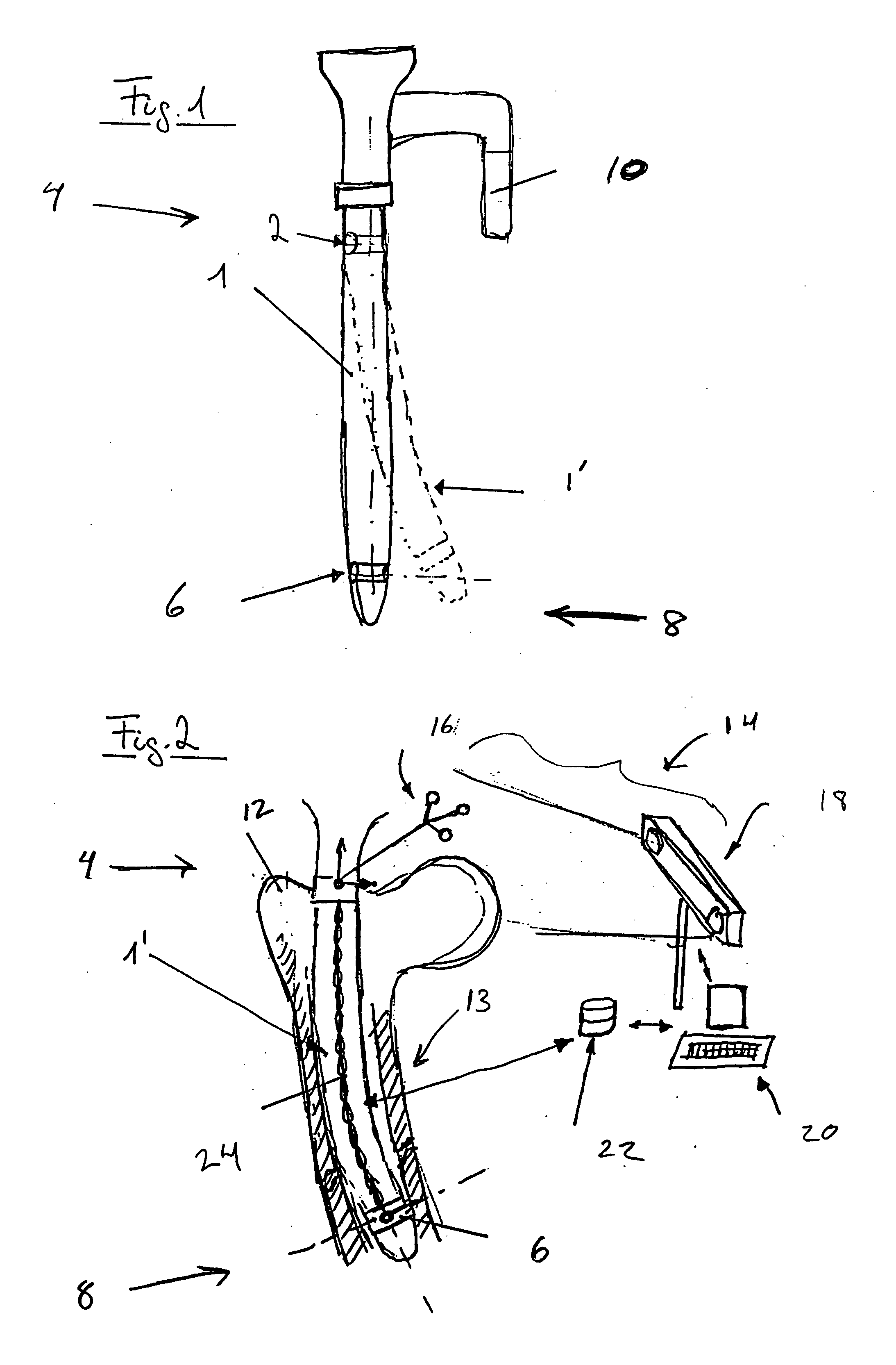
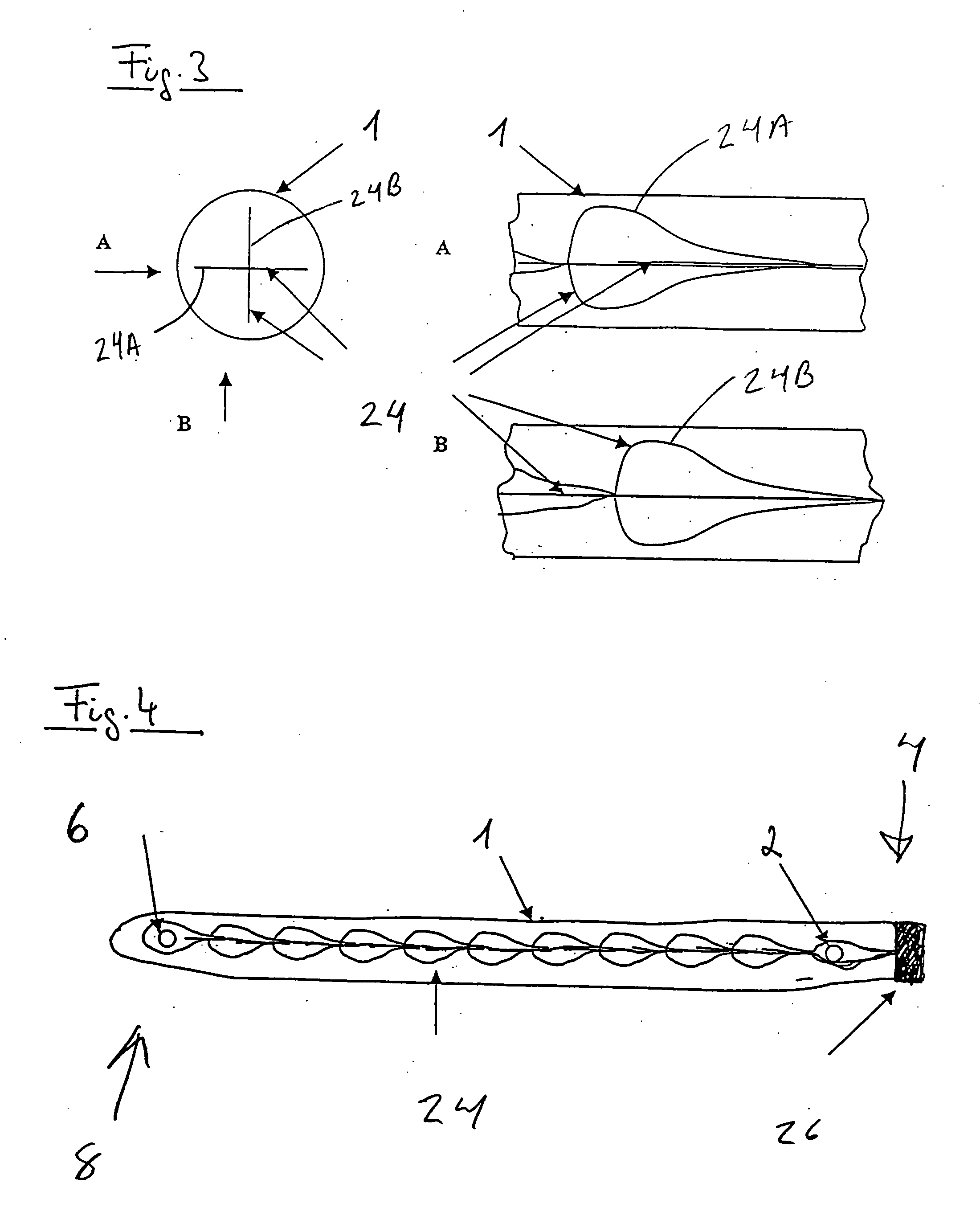
[0027]FIG. 1 illustrates the intramedullary pin 1 in its non-deformed shape and (by a broken line) a deformed intramedullary pin 1′. The intramedullary pin 1 can include an elongated shaft having a fixing bore 2 at its proximal end 4 and a fixing bore 6 at its distal end 8. Furthermore, the intramedullary pin 1 shown in FIG. 1 is attached to a positioning aid attachment 10, which facilitates insertion of the intramedullary pin into a bone 12.

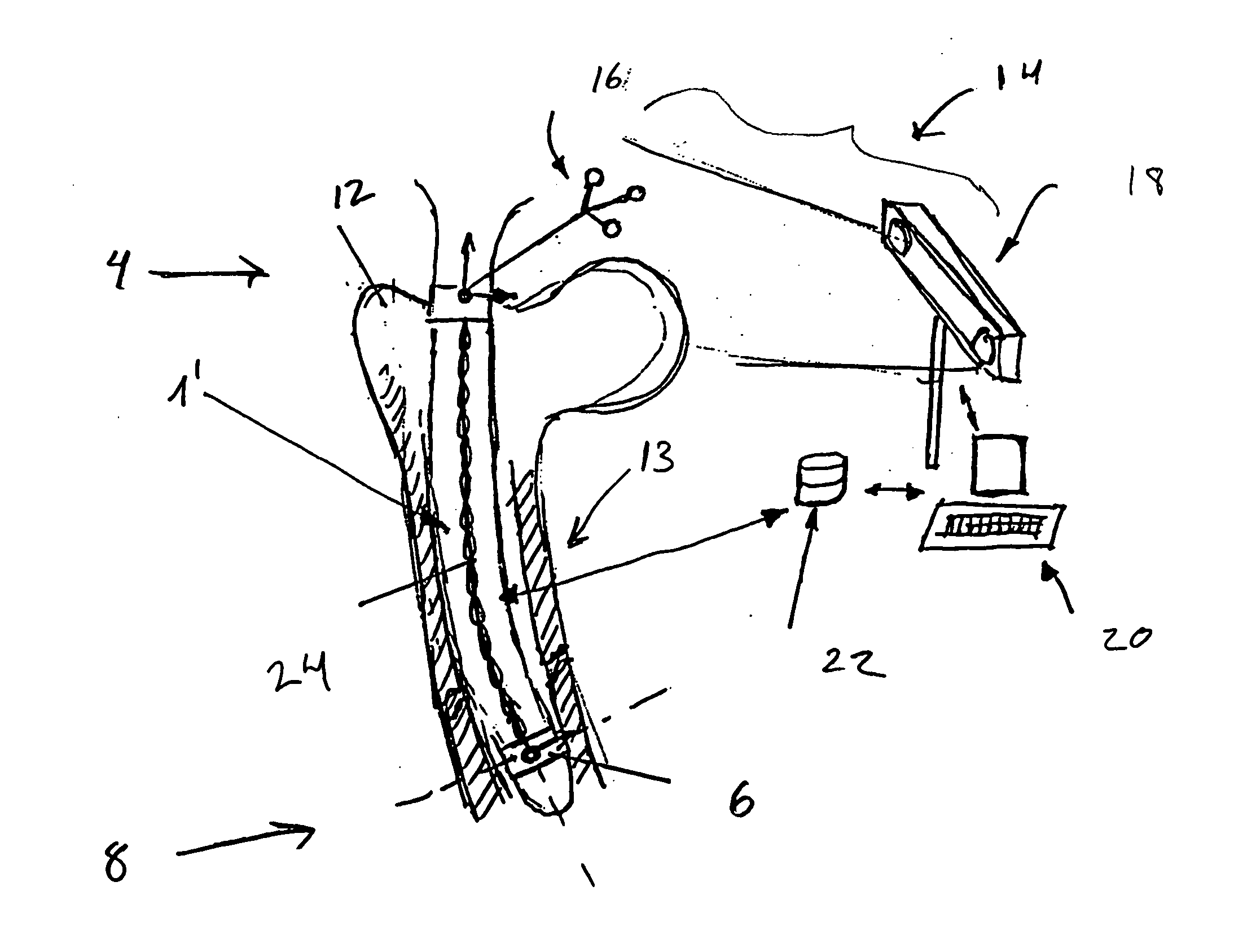
[0028] The pin 1′, inserted in a bone and thus deformed, is shown in FIG. 2. The bone 12 includes a bend 13, which the intramedullary pin follows when it is inserted into the bone. As a result of the bend 13, the fixing bore 6 comes to rest obliquely at the distal end 8. In order to determine the position and orientation of the fixing bore 6 and, therefore, to be able to precisely insert a fixing screw into the fixing bore 6, a tracking system 14 in accordance with the invention is employed. The tracking system 14 includes a reference structure...


PUM


Abstract

A tracking device for an intramedullary pin whose spatial position is determined and / or tracked in image-guided surgery, including a reference device at a proximal end of the intramedullary pin and a medical navigation system which locates the reference device and determines the orientation of the intramedullary pin from the proximal end. A deformation detection device detects deformations of the intramedullary pin and communicates the deformations to the navigation system. Also provided is a tracking method for determining or tracking the spatial position of an intramedullary pin in image-guided surgery, and to an intramedullary pin that includes a deformation detection device.

Description

RELATED APPLICATION DATA [0001] This application claims priority of U.S. Provisional Application No. 60 / 579,388 filed Jun. 14, 2004, which is hereby incorporated herein by reference in its entirety.FIELD OF THE INVENTION [0002] The present invention relates to the field of intramedullary pin tracking and, more particularly, to a method, apparatus and system for tracking an intramedullary pin and ascertaining a deformation of the pin as it is inserted into an object, such as a bone. BACKGROUND OF THE INVENTION [0003] The use of intramedullary pins is a known and established form of treatment for fractures in long bones. Intramedullary pins include fixing holes or bores at the proximal and distal ends of the intramedullary pin (the implant), and screws can be inserted into the fixing holes or bores in order to fix or attach the intramedullary pin to the fractured bone. [0004] One problem with conventional intramedullary pins is that the implanted intramedullary pin is deformed by the ...

Claims


Application Information

Patent Timeline
Patent Type & Authority Applications(United States)
IPC IPC(8): A61B19/00A61F2/38
CPCA61B19/52A61B19/5244A61B2019/467A61B2019/5483A61B2019/5255A61B2019/5272A61B2019/507A61B90/36A61B34/20A61B2034/107A61B2034/2055A61B2034/2072A61B2090/067A61B2090/3983
Inventor TUMA, GREGORWENDE, CHRISTIAN
Owner BRAINLAB
Why Eureka
Try Eureka