Lateral-approach artificial disc replacements

a lateral approach and disc technology, applied in the field of spine surgery, can solve the problems of reduced bone density, reduced bone density, and reduced ability to handle compression load, and achieve the effect of facilitating bone ingrowth and recovering more quickly

Inactive Publication Date: 2005-11-24
ANOVA
View PDF23 Cites 51 Cited by
  • Summary
  • Abstract
  • Description
  • Claims
  • Application Information

AI Technical Summary

Benefits of technology

[0011] The invention offers several important advantages. For one, the thick anterior longitudinal ligament (ALL) is preserved. Anterior approaches to the disc sacrifice the ALL. Since the ALL limits spinal extension and extension forces, it may help prevent extension forces on ADRs. The ALL may help prevent ADR extrusion. Disc space distraction tightens the ALL. Thus, once inserted, counter tension by the ALL may help to hold an ADR securely in place. Secure placement facilitates bone ingrowth.
[0012] The great vessels must be manipulated during an anterior approach. Furthermore, bulky devices cannot be left against the great vessels. Death from aneurysms caused by erosion of the great vessels against spinal devices has been reported. Lateral ADR insertion allows the use of larger plate-like extension on the device, as the great vessels lie over the anterior portion of the spine, not the lateral portion. The larger plate-like extensions, with more screws, hold the ADR more securely in place.
[0013] Furthermore, minimally invasive techniques have been developed for lateral approaches to the spine, enabling patients to recover more quickly.

Problems solved by technology

The nucleus becomes thinner and less able to handle compression loads.
The redundant annular fibers are less effective in controlling vertebral motion.
Current surgical treatments of disc degeneration are destructive.
These destructive procedures lead to acceleration of disc degeneration.
The first two groups of procedures compromise the treated disc.
The additional stress results in premature disc degeneration of the adjacent discs.

Method used


Image

  • Lateral-approach artificial disc replacements
  • Lateral-approach artificial disc replacements
  • Lateral-approach artificial disc replacements

Examples


Embodiment Construction

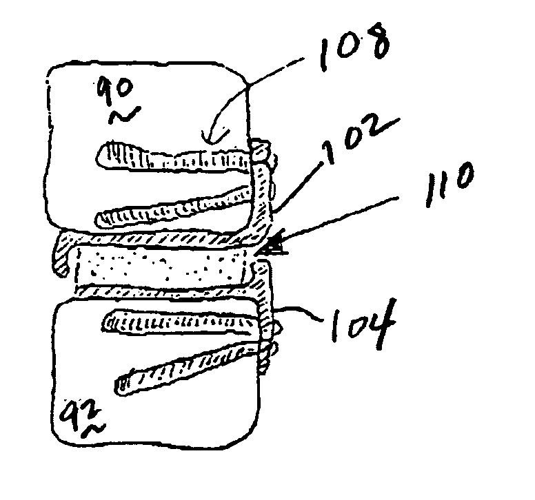
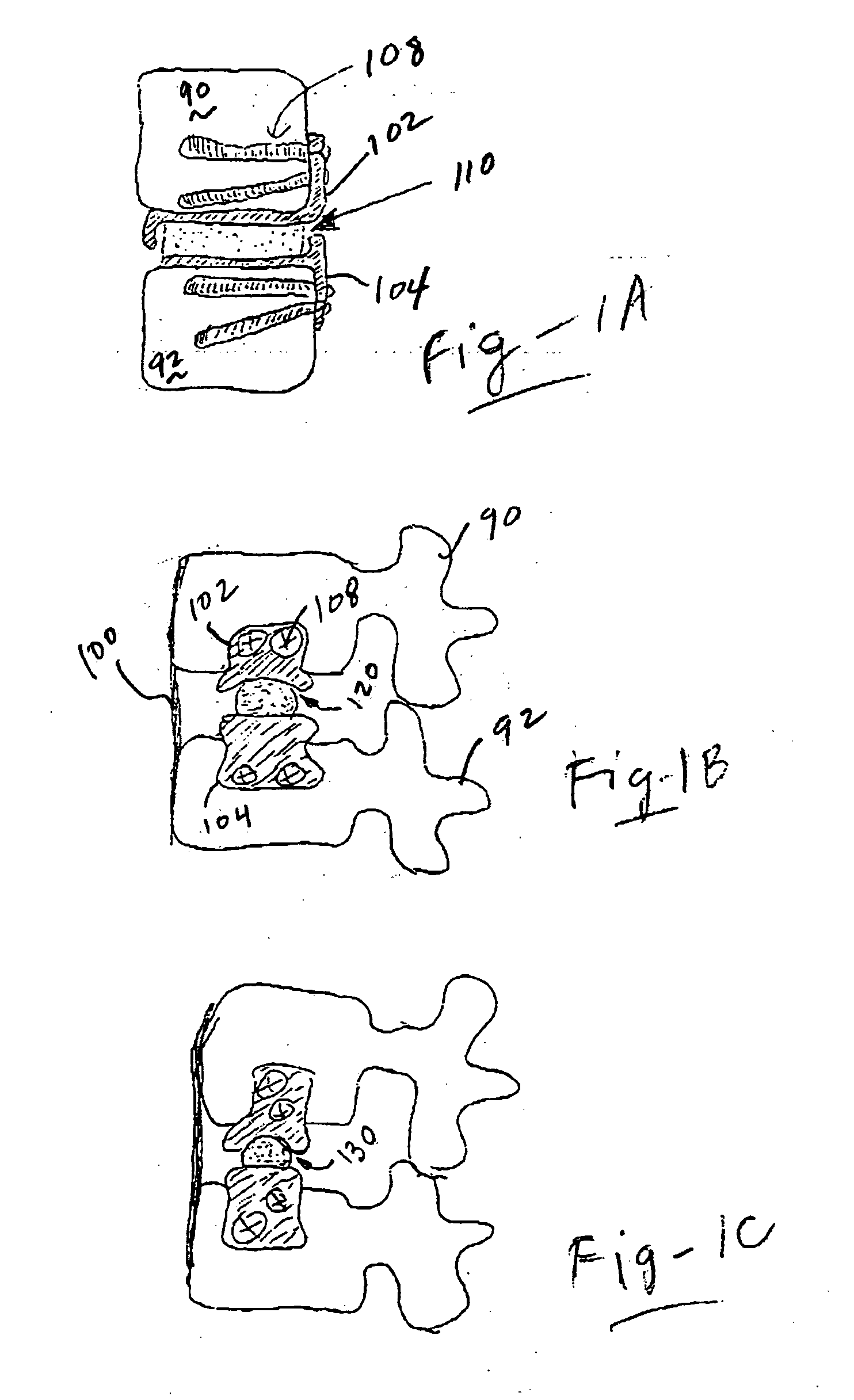
[0030]FIG. 1A is an A-P view of an artificial disc replacement using a lateral approach according to the invention. In the preferred embodiments, ADRs according to the invention feature relatively large, plate-like extensions fastened to the vertebrae 90, 92. These large plate-like extensions 102, 104 allow screws such as 108 to diverge or converge for greater pull-out strength. A spacer is used between these extensions. A polyethylene cylinder 110 is preferably used to avoid the thin sections of polyethylene found in some ADR designs. Thin sections of polyethylene risk fracture and the need for replacement as the poly becomes thin from wear. The ADR can be inserted in parts through a working cannula during minimally invasive surgery.

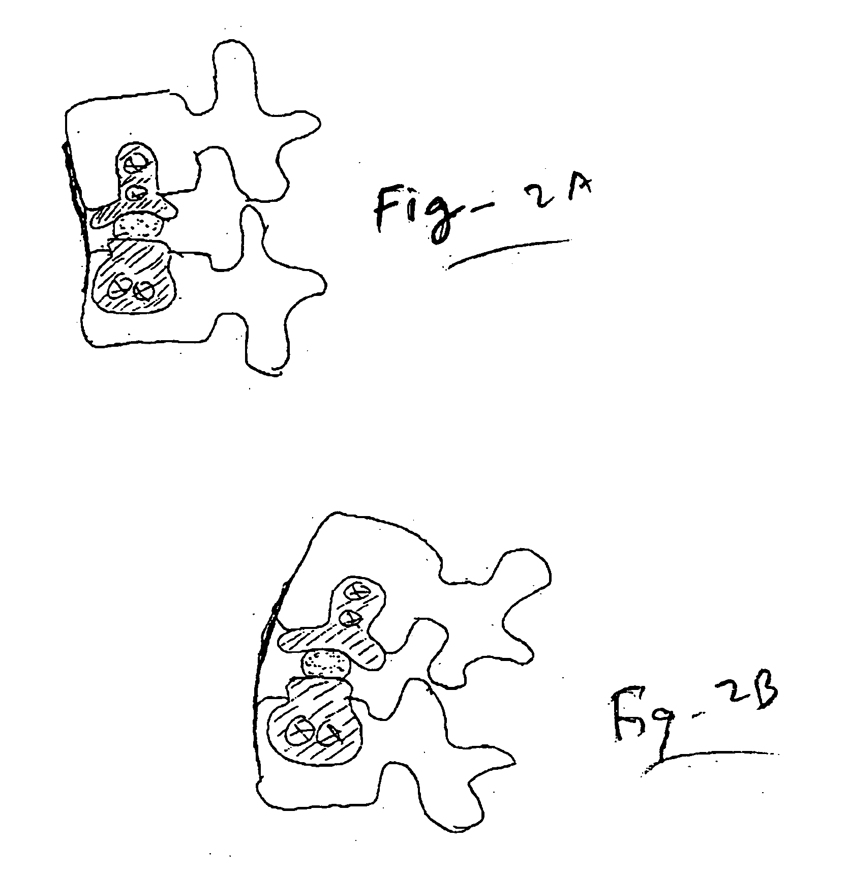
[0031]FIG. 1B is a lateral view of the device of FIG. 1A showing how the anterior longitudinal ligament (ALL, 100) remains in tact using approaches according to this invention. The system is semi-constrained, allowing flexion extension and limited tran...


PUM


Abstract

Artificial disc replacements (ADRS) are configured for implantation using a lateral, anterior-lateral, or posterior-lateral approach. A first component having a first segment resides in the disc space for articulation purposes, with a second segment adapted for fixation to the lateral outer surface of one of the vertebral bodies. A second component having a first segment resides in the disc space for articulation purposes, with a second segment adapted for fixation to the lateral outer surface of the other vertebral body. The first segments of the two components may articulate against one another without a spacer, or a spacer forming a mobile bearing may be disposed between the first segments of the two components. In the preferred embodiment, one or both of the two components are in the form of bent plates such that the second segment is positioned against a lateral wall for fixation. In the preferred embodiment, screws are used through the second segment and into a vertebral body. The screws are located in different vertical locations, and may diverge or converge vertically or horizontally to resist pull-out.

Description

REFERENCE TO RELATED APPLICATIONS [0001] This application claims priority from U.S. Provisional Patent Application Ser. No. 60 / 378,132, filed May 15, 2002; and is a continuation-in-part of U.S. patent application Ser. No. 10 / 413,028, filed Apr. 14, 2003. The entire contents of both applications are incorporated herein by reference.FIELD OF THE INVENTION [0002] This invention relates generally to spine surgery and, more particularly, to artificial disc replacements based upon a lateral approach. BACKGROUND OF THE INVENTION [0003] Premature or accelerated intervertebral disc degeneration is known as degenerative disc disease. A large portion of patients suffering from chronic low back pain are thought to have this condition. As the disc degenerates, the nucleus and annulus functions are compromised. The nucleus becomes thinner and less able to handle compression loads. The nucleus fibers become redundant as the nucleus shrinks. The redundant annular fibers are less effective in contro...

Claims


Application Information

Patent Timeline
Patent Type & Authority Applications(United States)
IPC IPC(8): A61F2/00A61F2/30A61F2/44
CPCA61F2/4425A61F2002/30224A61F2002/30301A61F2230/0095A61F2002/443A61F2230/0069A61F2002/30578
Inventor FERREE, BRET A.
Owner ANOVA
Why Eureka
Try Eureka