
Apparatus and method for resource allocation

Inactive Publication Date: 2005-11-24
TELEFON AB LM ERICSSON (PUBL)
View PDF7 Cites 104 Cited by
  • Summary
  • Abstract
  • Description
  • Claims
  • Application Information

AI Technical Summary

Benefits of technology

[0035] An advantage with this method is that it can be ensured that Active Queue Management has not asked TCP to reduce its load at the same time as Radio Resource Management is providing more resources. The risk of conflicting actions is removed. As a consequence, the allocated capacity is better utilized, because the TCP load is not reduced prior to the up-switch of the capacity.
[0043] An advantage is because Active Queue Management is informed of the rate reduction in advance, it can start to reduce the source rate before the down-switch, thereby avoiding excessive buffering delays or buffer overflow.
[0044] Further, because the link rate is still high when the Active Queue Management actions start, the Active Queue Management actions (packet drop or ECN marking) take effect faster.

Problems solved by technology

The problem with earlier solutions is that they have not realised that this has to be done.
They have not understood that problems, such as oscillations, may occur in systems where Active Queue Management and Radio Resource Management work independently.
However, this is not in line with the reality of a resource limited system.
A small buffer, on the other hand, makes it difficult for Radio Resource Management to use the buffer fill-level as a measurement for prediction of future capacity needs of a link.

Method used


Image

  • Apparatus and method for resource allocation
  • Apparatus and method for resource allocation
  • Apparatus and method for resource allocation

Examples


Embodiment Construction

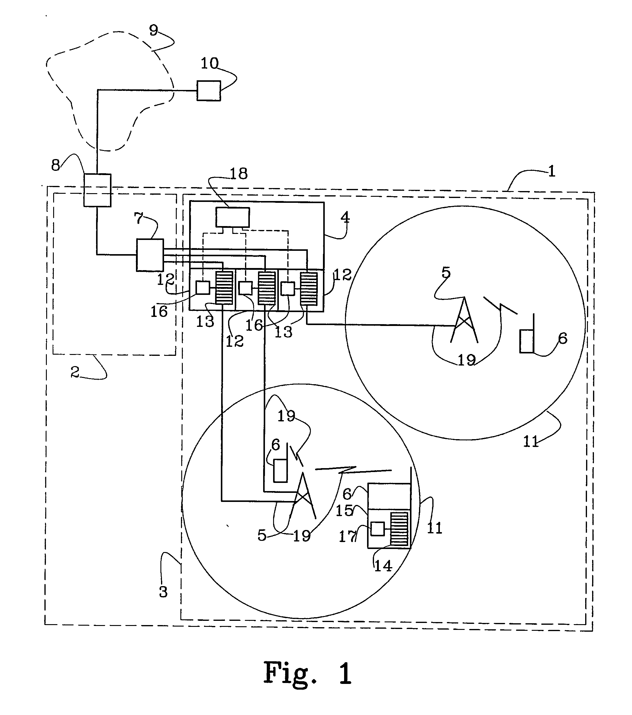
[0047]FIG. 1 illustrates schematically, according to the invention, a Universal Mobile Telecommunications system (UMTS) network 1 using Wideband Code Division Multiple Access (WCDMA). The UMTS network 1 includes a core network 2 and a UMTS Terrestrial Radio Access Network (UTRAN) 3. The UTRAN 3 includes a number of Radio Network Controllers (RNC) 4—of which only one is drawn for the sake of clarity. Each of the Radio Network Controllers 4 is coupled to a set of neighbouring base stations, normally called Node Bs 5. Each Node B 5 is responsible for a given cell 11 and the controlling Radio Network Controller 4 is responsible for routing user and signalling data between that Node B 5 and the core network 2. A general outline of the UTRAN 3 is given in Technical Specification TS 25.401 V3.2.0 of the 3rd Generation Partnership Project. FIG. 1 also illustrates mobile terminals or User Equipments (UE) 6, a Serving GPRS Support Node (SGSN) 7 and a GPRS Gateway Support Node (GGSN) 8. The Se...


PUM


Abstract

The present invention relates to a method and an arrangement for resource allocation in a packet transmission network including at least one link (19). According to the invention the following steps are performed: Determining link resource status. If link congestion is determined then: determining if it is possible to allocate more link capacity, allocating more link capacity when it is possible to allocate more link capacity, and alleviating link congestion using Active Queue Management when it is not possible to allocate more link capacity.

Description

TECHNICAL FIELD OF THE INVENTION [0001] The present invention relates to the handling of link and cell congestion in packet transmission networks and more particularly to the early detection of congestion and the implementation of mechanisms for obviating the consequences of congestion. DESCRIPTION OF RELATED ART [0002] In packet based communication systems, i.e. in which information to be transmitted is divided into a plurality of packets and the individual packets are sent over a communication network, variable bit rates occur. It is therefore known to provide queue buffers at various points in the network to accommodate for sudden bursts in the load. [0003] A phenomenon that is known in packet transmission networks is that of link congestion. Link congestion implies a state in which it is not possible to readily handle the number of data packets that are required to be transported over that connection or link. As a consequence of congestion at a given link, the number of data pac...

Claims


Application Information

Patent Timeline
IPC IPC(8): H04L12/54H04L47/32
CPCH04L12/5695H04L47/10H04L47/14H04L47/15H04L47/193H04L47/29H04W72/04H04L47/822H04L47/823H04L47/824H04W24/00H04W28/08H04W28/18H04L47/32H04L47/70H04W28/02H04L47/83H04W8/04
Inventor WIBERG, NICLASSTROMSOE, MIKAELPEISA, JANNESAGFORS, MATS
Owner TELEFON AB LM ERICSSON (PUBL)
Features
  • Generate Ideas
  • Intellectual Property
  • Life Sciences
  • Materials
  • Tech Scout
  • Unparalleled Data Quality
  • Higher Quality Content
  • 60% Fewer Hallucinations
Learn More