High power density thermoelectric systems

a thermoelectric system and high-power technology, applied in the manufacture/treatment of thermoelectric devices, machines/engines, lighting and heating apparatus, etc., can solve the problems of low efficiency, high cost, low power density, etc., and achieve the effect of reducing the construction complexity and cost of sschp devices, reducing cost, and maintaining or improving efficiency gains

Inactive Publication Date: 2005-12-01
GENTHERM INC
View PDF85 Cites 32 Cited by
  • Summary
  • Abstract
  • Description
  • Claims
  • Application Information

AI Technical Summary

Benefits of technology

[0040] In general, this disclosure describes a new family of SSCHP configurations. These configurations achieve compact, high-efficiency energy conversion and can be relatively low cost. Generally, several embodiments are disclosed wherein TE elements or modules (collectively called elements in this text) are sandwiched between heat exchangers. The TE elements are advantageously oriented such that for any two elements sandwiching a heat exchanger, the same temperature type side faces the heat exchanger. For example, the cooler side of each of the TE elements sandwiching a heat exchanger face the same heat exchanger or shunt, and thus each other. In a group of configurations, at least one working medium is passed sequentially through at least two heat exchangers so that the cooling or heating provided is additive on the working medium. This configuration has the added benefit that it utilizes the advantages of thermal isolation, as described in U.S. Pat. No. 6,539,725, in manufactureable systems that exhibit high system efficiency and power density as noted in the references above. As explained in that patent, in general, a TE device achieves increased or improved efficiency by subdividing the overall assembly of TE elements into thermally isolated subassemblies or sections. For example, the heat exchangers may be subdivided so as to provide thermal isolation in the direction of working medium flow. For example, a TE system has a plurality of TE elements forming a TE array with a cooling side and a heating side, wherein the plurality of TE elements are substantially isolated from each other in at least one direction across the array. Preferably, the thermal isolation is in the direction of the working media flow. This thermal isolation can be provided by having a heat exchanger configured in sections such that the heat exchanger has portions which are thermally isolated in the direction of working fluid flow.
[0043] The embodiments described in this application lower the construction complexity and cost of SSCHP devices while still maintaining or improving efficiency gains from thermal isolation.
[0044] Also disclosed are several embodiments for reducing cost by using less TE material and facilitating operation closer to peak efficiency. Many embodiments achieve a substantial reduction in parasitic losses (see FIGS. 12-31).
[0047] Preferably, the thermoelectric elements are constructed to be quite thin, such as from 5 microns, to 1.2 mm, from 20 microns to 200 microns for superlattice and hetrostructure thermoelectric designs, and in another embodiment from 100 to 600 microns. These designs provide for significant reduction in the usage of thermoelectric material.

Problems solved by technology

Commercial usage has been limited because such systems have been too costly for the function performed, and have low power density so SSCHP systems are larger, more costly, less efficient and heavier than has been commercially acceptable.
However, Thermoelectric (TE) device usage has been limited by low efficiency, low power density and high cost.
As a result, the cost of TE modules for efficient operation is significantly higher and the resulting systems are substantially larger.
An important limitation in thermoelectric systems is that as, for example, the length LC is decreased for fixed AC, the ratio of the parasitic resistive losses to TE material losses, φC becomes relatively large.

Method used


Image

  • High power density thermoelectric systems
  • High power density thermoelectric systems
  • High power density thermoelectric systems

Examples


Embodiment Construction

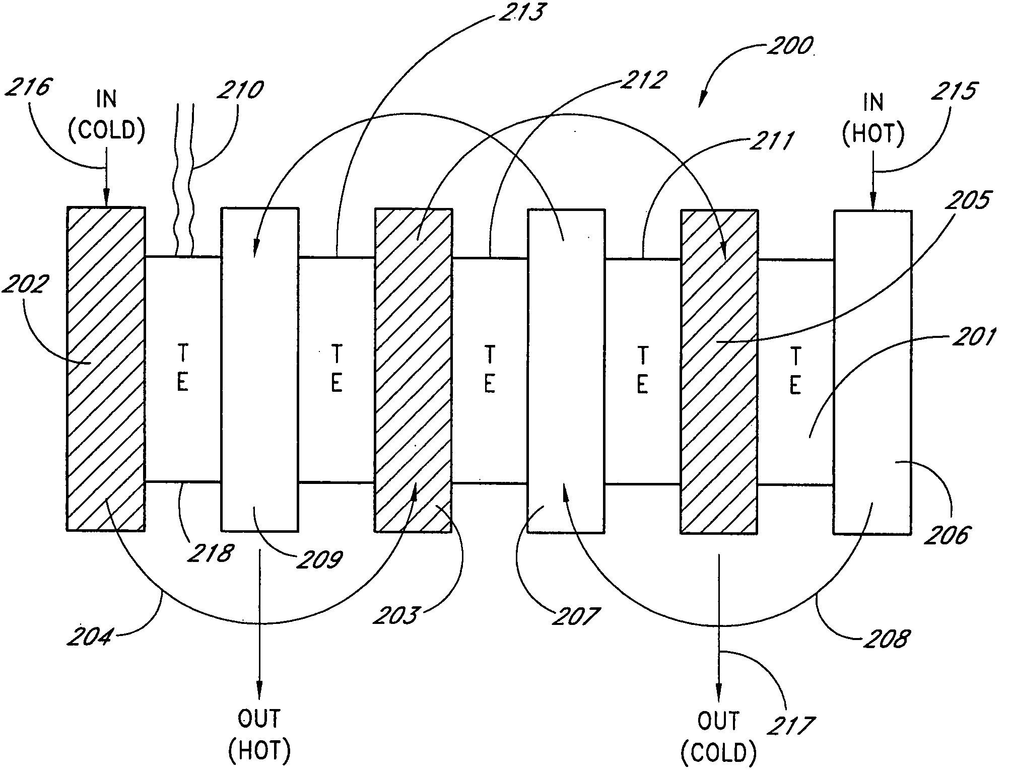
[0090] In the context of this description, the terms thermoelectric module and TE module are used in the broad sense of their ordinary and accustomed meaning, which is (1) conventional thermoelectric modules, such as those produced by Hi Z Technologies, Inc. of San Diego, Calif., (2) quantum tunneling converters, (3) thermionic modules, (4) magneto caloric modules, (5) elements utilizing one, or any combination of thermoelectric, magneto caloric, quantum, tunneling and thermionic effects, (6) any combination, array, assembly and other structure of (1) through (6) above. The term thermoelectric element, is more specific to indicate an individual element that operates using thermoelectric, thermionic, quantum, tunneling, and any combination of these effects.

[0091] In the following descriptions, thermoelectric or SSCHP systems are described by way of example. Nevertheless, it is intended that such technology and descriptions encompass all SSCHP systems.

[0092] Accordingly, the inventi...


PUM


Abstract

A number of compact, high-efficiency and high-power density thermoelectric systems utilizing the advantages of thermal isolation are described. Such configurations exhibit high system efficiency and power density. Some configurations exhibit a substantial reduction in the amount of thermoelectric material required.

Description

CONTINUING APPLICATION DATA [0001] This application is a continuation of U.S. patent application Ser. No. 10 / 642,773 filed Aug. 18, 2003, which is a continuation-in-part of U.S. patent application Ser. No. 10 / 227,398 filed Aug. 23, 2002, and a continuation-in-part of U.S. patent application Ser. No. 10 / 405,001, filed Mar. 31, 2003, which is a continuation of U.S. patent application Ser. No. 09 / 844,818, filed Apr. 27, 2001, which is related to and claims the benefit of U.S. Provisional Patent Application No. 60 / 267,657 filed Feb. 9, 2001.BACKGROUND OF THE INVENTION [0002] 1. Field of the Invention [0003] This disclosure relates to improved configurations for solid-state cooling, heating and power generation systems. [0004] 2. Description of the Related Art [0005] Thermoelectric devices (TEs) utilize the properties of certain materials to develop a temperature gradient across the material in the presence of current flow. Conventional thermoelectric devices utilize P-type and N-type se...

Claims


Application Information

Patent Timeline
Patent Type & Authority Applications(United States)
IPC IPC(8): F02G1/043F25B21/02F25B21/04F25B33/00H01L35/00H01L35/28H01L35/30H01L35/32H01L35/34H01L37/00
CPCF02G1/043F25B21/02F25B21/04H01L35/32F25B2321/021H01L35/00H01L35/30F25B33/00H10N10/00H10N10/17H10N10/13
Inventor BELL, LON E.
Owner GENTHERM INC
Why Eureka
Try Eureka