Electric drive system having DC bus voltage control

a technology of electric drive and voltage control, which is applied in the direction of electric motor propulsion, electric generator control, motor/generator/converter stopper, etc., can solve the problems of insufficient acceleration and regenerative braking capacity of battery array, complex and expensive components of controllers,

Active Publication Date: 2005-12-01
CATERPILLAR INC
View PDF23 Cites 46 Cited by
  • Summary
  • Abstract
  • Description
  • Claims
  • Application Information

AI Technical Summary

Benefits of technology

[0008] In one aspect, the present disclosure provides an article having a computer readable medium with a control algorithm recorded thereon. The control algorithm includes means for compensating for a change in power demand on a DC bus, which has an electric motor and a generator connected therewith. The means for compensating includes, means for

Problems solved by technology

Although the controller of the '620 patent may maintain a sufficiently constant state of charge of the battery array, the controller may require complex and expensive co

Method used


Image

  • Electric drive system having DC bus voltage control
  • Electric drive system having DC bus voltage control
  • Electric drive system having DC bus voltage control

Examples


Embodiment Construction

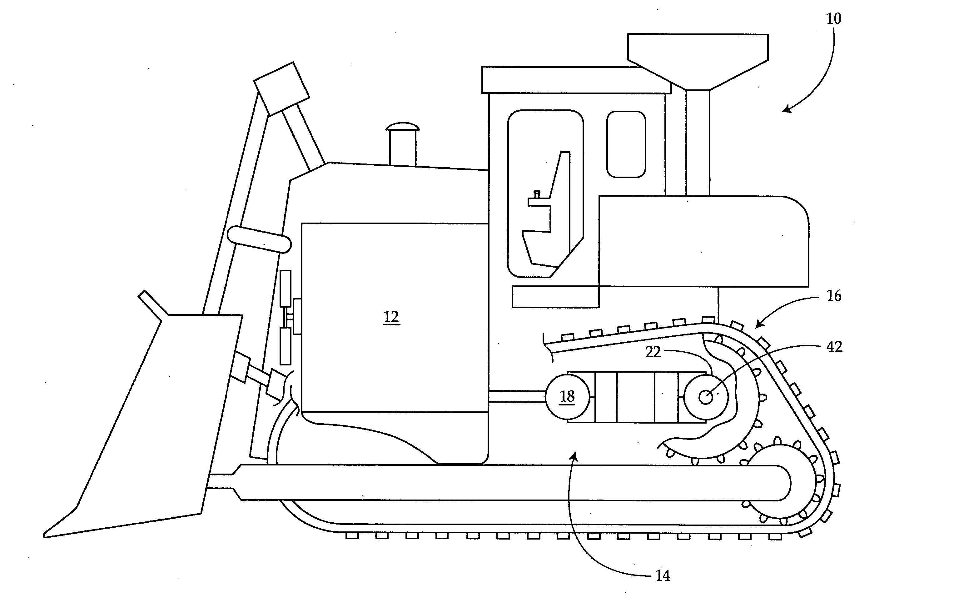
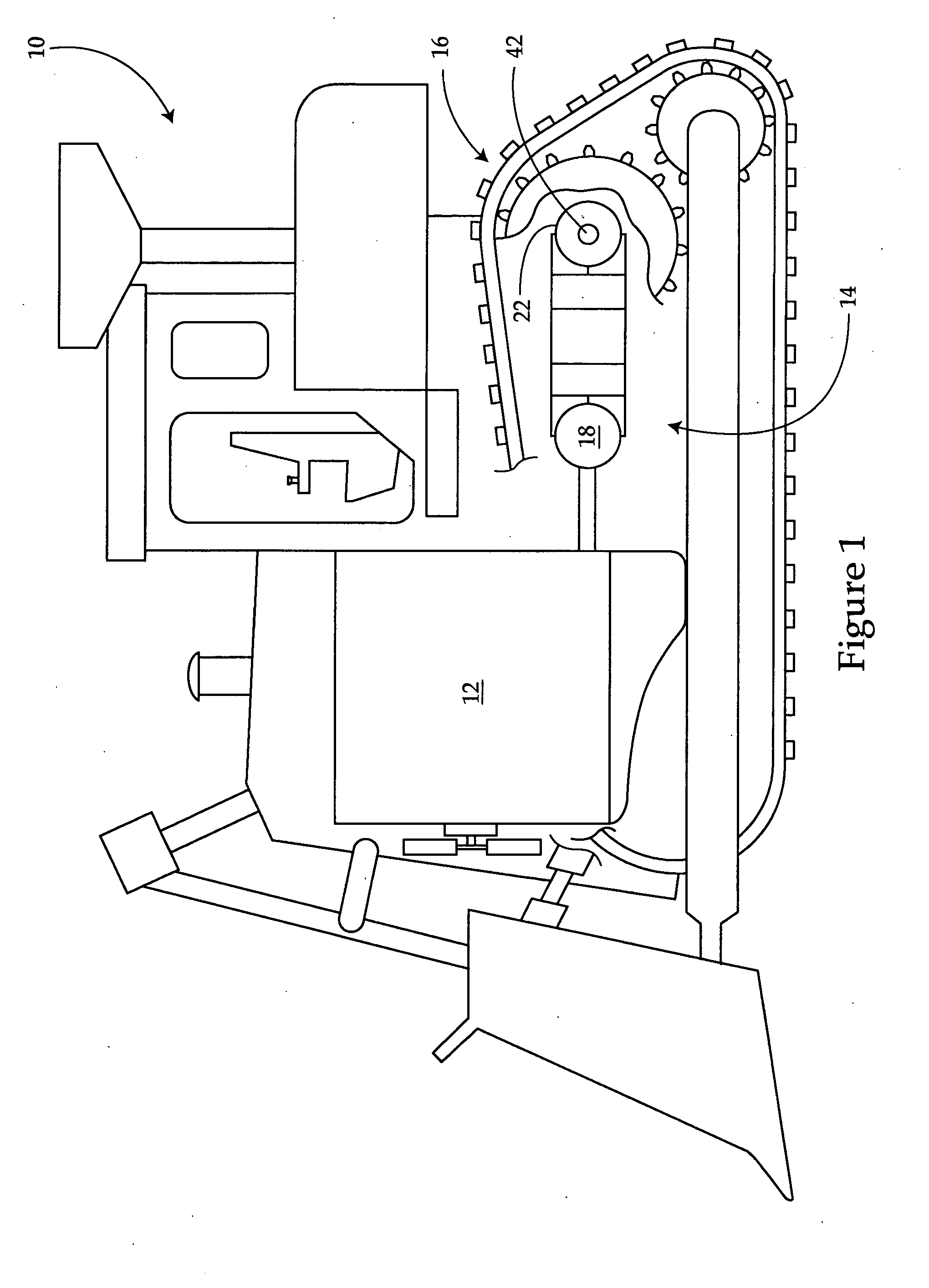
[0015]FIG. 1 illustrates a work machine 10 having a power source 12 and an electric drive 14 connected to a traction device 16. Work machine 10 may be a mobile machine that performs some type of operation associated with an industry such as mining, construction, farming, transportation, or any other industry known in the art. For example, work machine 10 may be an earth moving machine, a marine vessel, an aircraft, an on-highway passenger vehicle, or any other suitable mobile work machine.

[0016] Power source 12 may be an engine, such as a diesel engine, a gasoline engine, a natural gas engine, or another appropriate engine. It is contemplated that electric drive 14 may be used with another type of power source such as, for example, a fuel cell. Power source 12 may have a maximum rotational speed limit.

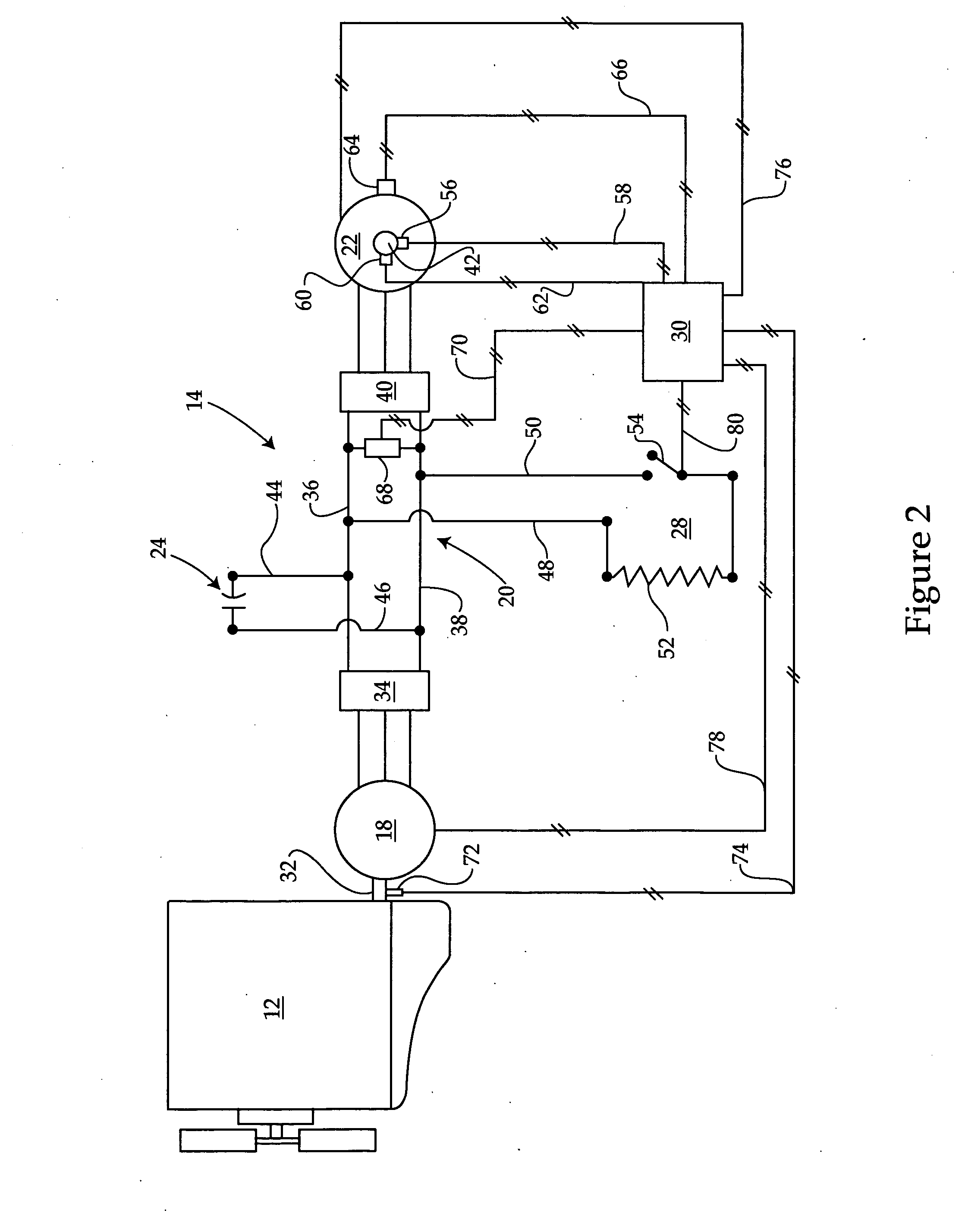
[0017] As illustrated in FIG. 2, electric drive 14 may include a generator 18 configured to produce an output power directed to a common bus 20 shared with a motor 22, an energy stor...


PUM


Abstract

An electric drive system has a power source and a generator operatively connected to the power source. The electric drive system also has at least one energy storage device such as a capacitor configured to store a supply of power. The electric drive system further has a common bus configured to direct the power output to the capacitor. The electric drive system also has at least one motor configured to receive power from the common bus. A controller for the electric drive system is provided, having an article therewith having a computer readable medium with a control algorithm recorded thereon. The control algorithm includes means for compensating for a change in power demand on a DC bus of the electric drive system

Description

CROSS-REFERENCE TO RELATED APPLICATIONS [0001] The present application is a Continuation-in-Part of U.S. patent application Ser. No. 10 / 852,137, filed May 25, 2004.TECHNICAL FIELD [0002] The present disclosure relates generally to a control system and method for an electric drive system in a work machine and, relates more particularly to a control system utilizing an algorithm and method for compensating for changes in power demand in an electric drive system having DC bus voltage control. BACKGROUND [0003] Work machines such as, for example, wheel loaders, track type tractors, and other types of heavy machinery are used for a variety of tasks. These work machines include a power source, which may be, for example, an engine such as a diesel engine, a gasoline engine, or a natural gas engine, that provides the power required to complete these tasks. To efficiently perform these tasks, the power source may be coupled to a generator to produce an electrical power output supplied to one...

Claims


Application Information

Patent Timeline
IPC IPC(8): B60K1/00E02F9/20B60K6/46B60L50/13B60L50/15B60W10/08B60W20/00B61C9/38H01M10/48H02P9/04
CPCB60K6/46B60L11/123B60L2220/18B60W10/08B60W10/26B60W20/00B60L2200/40H01M10/482Y02T10/6217Y02T10/7022Y02T10/7077Y02T90/16B60W2300/17B60L50/61Y02T10/62Y02T10/70Y02E60/10B60W20/10Y02T10/7072
Inventor SOPKO, TOMKURAS, BRIANGUVEN, MUSTAFA
Owner CATERPILLAR INC
Why Eureka
Try Eureka