
Fuel injector with and without pressure ampification with a controllable needle speed and method for the controlling thereof

a technology of fuel injector and needle speed, which is applied in the direction of fuel injection apparatus, combustion engine, charge feed system, etc., can solve the problems of reducing the effective braked mass of the armature, and affecting the kinetic energy of the armatur

Inactive Publication Date: 2005-12-01
ROBERT BOSCH GMBH
View PDF10 Cites 11 Cited by
  • Summary
  • Abstract
  • Description
  • Claims
  • Application Information

AI Technical Summary

Benefits of technology

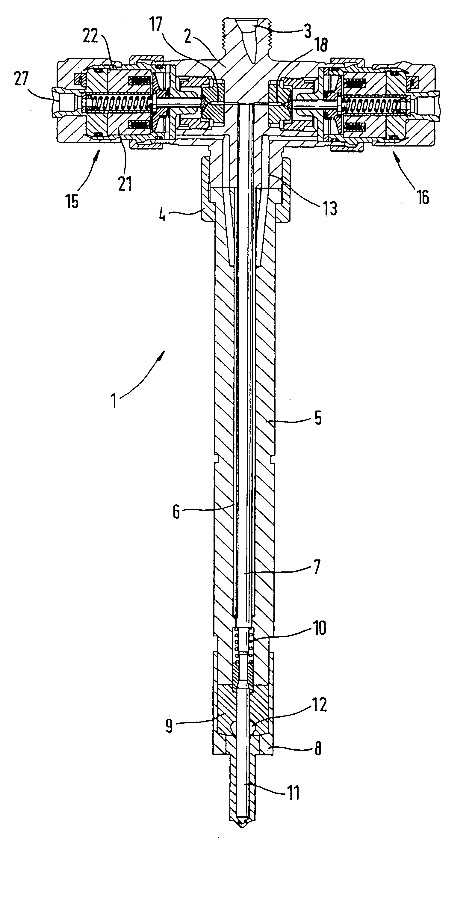
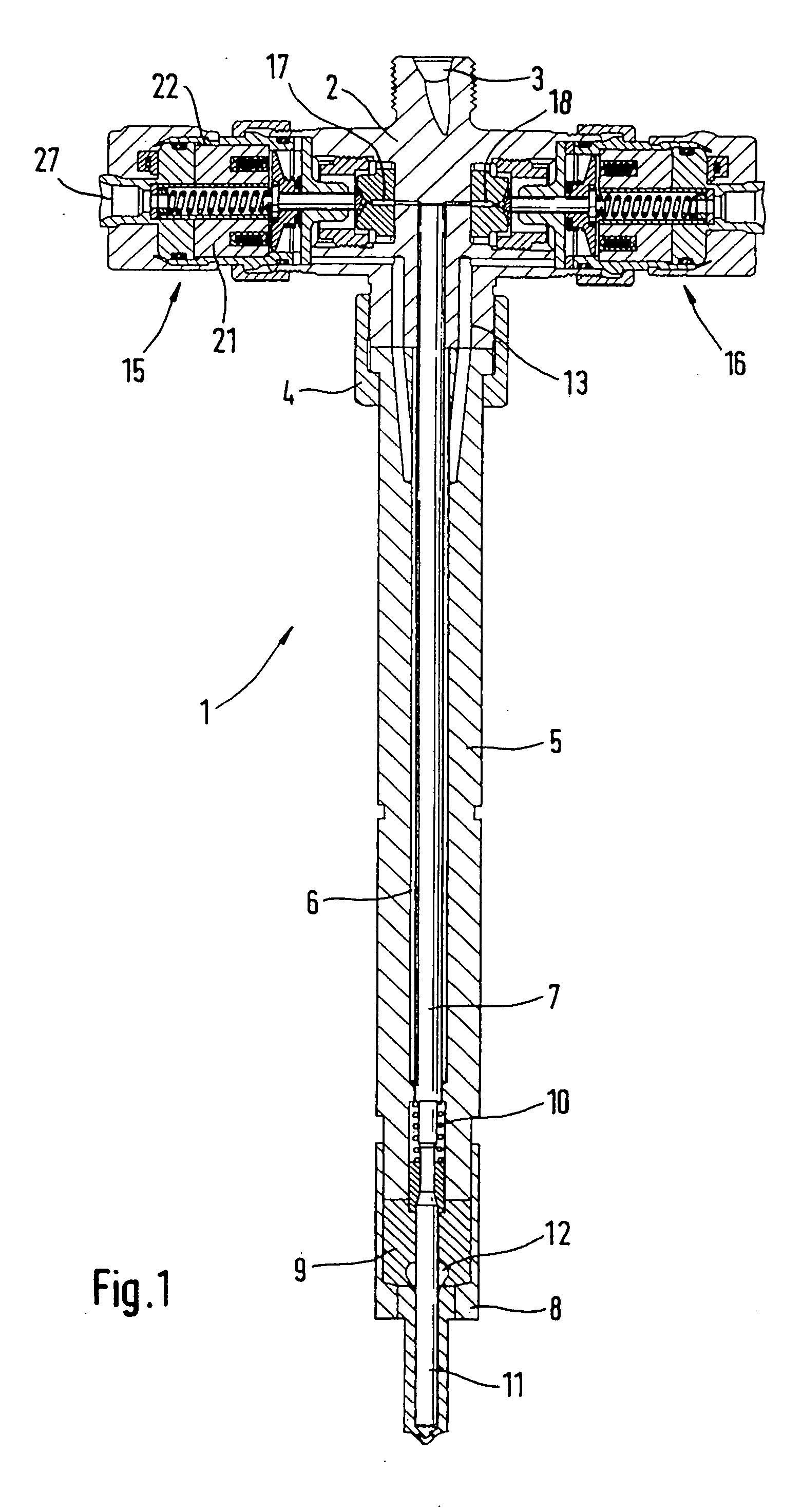
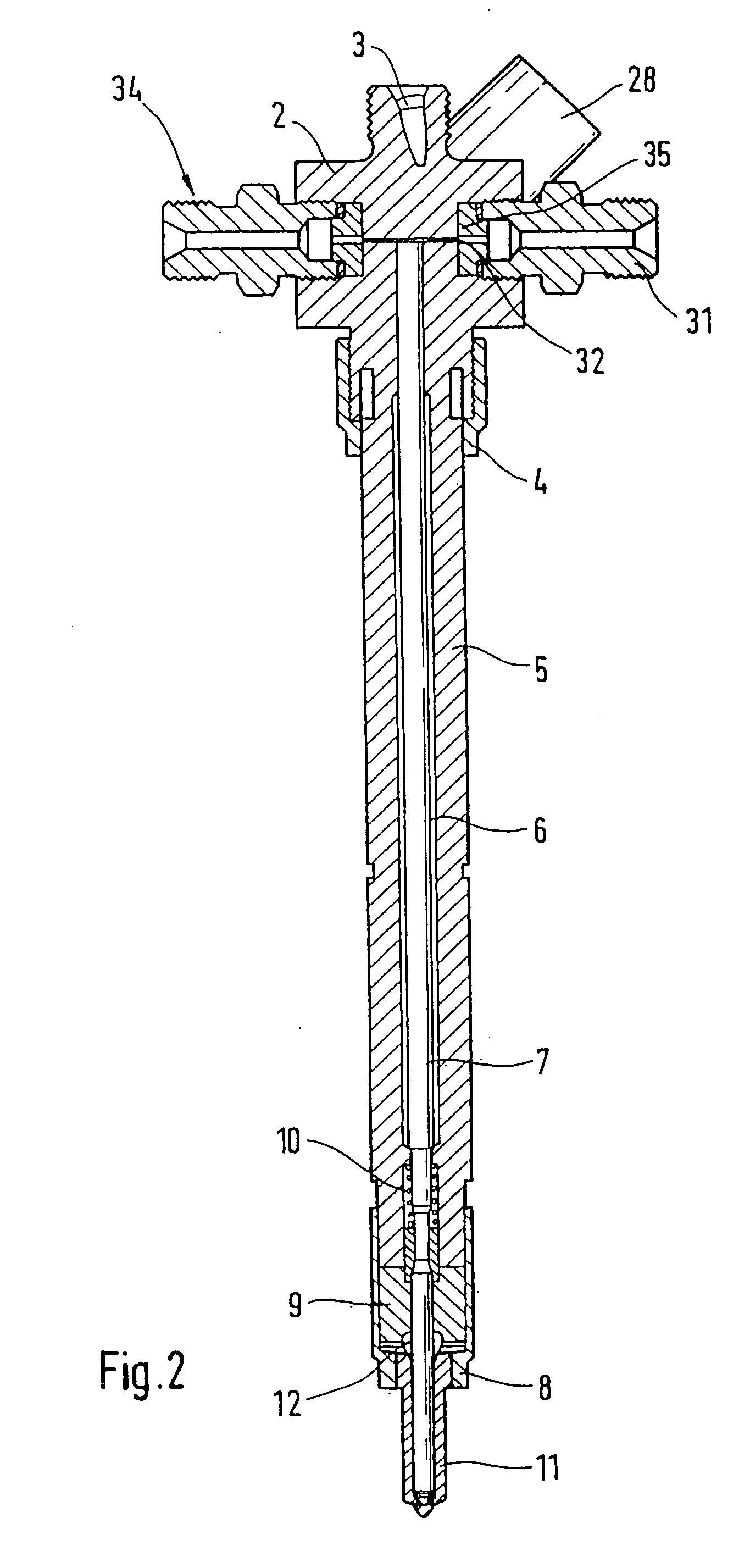
The invention relates to a new design for fuel injectors of internal combustion engines that can comply with current and future exhaust regulations. The design allows for multiple injections with precise control over the pressure increase in the combustion chamber, which is important for emissions control. The design includes a solenoid valve and a control chamber that can be actuated by a pilot injection to control the pressure increase. The design also includes two outlet throttles that can be triggered individually or jointly to further control the pressure increase and improve the stability of the injection system. The technical effects of the invention include improved emissions control, reduced noise levels, and improved fuel injector performance.

Problems solved by technology

The use of two-part armatures reduces their effectively braked mass and therefore reduces the kinetic energy of the armature striking the valve seat and thus causing the armature chatter.
Since they require an iterative adjustment that must be carried out in steps, these embodiments are costly, are difficult to automate, and therefore extend the cycle times that the manufacture of such solenoid valves requires.
These components, however, only permit the achievement of very low opening and closing speeds of an injection valve element, which can be embodied as a nozzle needle.
In multiple injections, it is therefore not possible to use different needle opening speeds to influence the pressure increase, which is decisive with regard to emissions, in such a way that a pilot injection (PI) occurs very close to the main injection phase without influencing the subsequent injections in a functionally critical manner.

Method used


Image

  • Fuel injector with and without pressure ampification with a controllable needle speed and method for the controlling thereof
  • Fuel injector with and without pressure ampification with a controllable needle speed and method for the controlling thereof
  • Fuel injector with and without pressure ampification with a controllable needle speed and method for the controlling thereof

Examples


first embodiment

[0007] In the design according to the invention, the valve body can be associated with two control elements that function as actuators. One of the solenoid valves that are used as actuators can open a very small outlet throttle for a pilot injection of fuel into the combustion chamber of an autoignition internal combustion engine. The pressure oscillations produced can be kept very low by means of the quantity that the very small outlet throttle allows to flow out of the injection system comprised of the high-pressure reservoir (common rail), the supply line, and the fuel injector. The smaller these pressure oscillations can be kept, the less influence the pressure oscillations have on the possible second pilot injection or the main injection phase following the pilot injection. This gives subsequent injections a significantly greater cyclical stability with regard to the pressure increase and significantly improves the maintenance of extremely small quantities injected into the com...

first exemplary embodiment

[0017]FIG. 4 shows an enlargement of the valve body of the fuel injector according to the invention in the first exemplary embodiment,

[0018]FIG. 4a shows an enlargement of an armature rod guide, which is contained in the valve body 2,

[0019]FIG. 5 shows another exemplary embodiment of the fuel injector proposed according to the invention, with a double-switching solenoid valve,

[0020]FIG. 6.1 shows a first power supply curve for executing a pilot injection and a slowly triggered nozzle needle, and a second power supply curve of a main injection with a triggered nozzle needle,

[0021]FIG. 6.2 shows the valve strokes that occur according to power supply curves in FIG. 6.1, plotted over the time axis,

[0022]FIG. 6.3 shows a first power supply curve for a pilot injection and a slowly moved nozzle needle, a second power supply curve for an additional pilot injection and a slow nozzle needle speed, and a main injection with a rapidly triggered nozzle needle,

[0023]FIG. 6.4 shows the valve ...


PUM


Abstract

A fuel injector in injection systems for internal combustion engines having a valve body containing a control chamber that can be pressure-relieved and can be acted on with fuel via an inlet throttle and can be pressure-relieved via an outlet throttle. A first actuator can actuate a closing element. The valve body is connected to a holding body that has a nozzle body connected to it, which encompasses an injection valve element. In order to relieve the pressure in the control chamber, an additional, second outlet throttle is provided, whose closing element can be actuated either by an additional actuator or as a function of the power supply to a double-switching actuator.

Description

TECHNICAL FIELD [0001] Fuel injectors of internal combustion engines execute a stroke-controlled or pressure-controlled injection of highly pressurized fuel into the combustion chamber of an engine. In order to comply with current and future exhaust regulations for internal combustion engines, it has become necessary to execute multiple injections (preinjections, main injections, and secondary injections). The time interval between these individual injections should be as short as possible and should at the same time exert as little influence as possible on the subsequent injection. A pilot injection, which precedes the main injection phase and is intended for conditioning the combustion chamber should not influence a subsequent main injection phase with regard to the pressure increase relevant to emissions. PRIOR ART [0002] The subject of DE 196 50 865 A1 is a solenoid valve for controlling the fuel pressure in the control pressure chamber of an injection valve element, for example...

Claims


Application Information

Patent Timeline
Patent Type & Authority Applications(United States)
IPC IPC(8): F02M45/02F02M47/00F02M45/08F02M45/12F02M47/02F02M57/02F02M59/10F02M59/46F02M61/20F02M63/00
CPCF02M45/02F02M45/08F02M45/12F02M47/027F02M57/025F02M59/105F02M63/0064F02M63/0015F02M63/0017F02M63/0026F02M63/004F02M63/0043F02M63/0049F02M61/205F02M63/0022F02M47/02F02M59/46F02M61/10
Inventor BRENK, ACHIMKROPP, MARTINMACK, MANFREDHAMMER, JUERGENTAMPE, REINHARDBASTIAN, HEIKE
Owner ROBERT BOSCH GMBH
Learn More