Stepping motor for use in high-temperature environments

a stepping motor and high-temperature environment technology, applied in the direction of magnetic circuit rotating parts, instruments, magnetic circuit shapes/forms/construction, etc., can solve the problems of deteriorating the performance failing to achieve a stable motor performance, etc., to achieve the effect of functioning without deterioration in performance, preventing the deterioration of the stepping motor, and high sliding ability

Active Publication Date: 2005-12-01
MINEBEAMITSUMI INC
View PDF6 Cites 20 Cited by
  • Summary
  • Abstract
  • Description
  • Claims
  • Application Information

AI Technical Summary

Benefits of technology

[0010] The present invention has been made in light of the above problem, and it is an object of the present invention to provide a stepping motor which duly functions without deterioration in performance when used in high-temperature and / or frictional heat generating environments.
[0011] In order to achieve the object described above, according to an aspect of the present invention, there is provided a stepping motor which comprises: a stator assembly; a rotor assembly rotatably disposed inside the stator assembly, and including a rotary shaft rotatably supported by bearings, a sleeve fixedly attached onto the rotary shaft, and at least one magnet disposed outside the sleeve; and a preloading mechanism disposed between the sleeve and one of the bearings, and including a coil spring, and a spring holder composed of outer and inner cases each shaped in a cup-like configuration, and adapted to house the coil spring. In the stepping motor described above, the spring holder of the preloading mechanism is formed of reinforced polyamide resin, and a washer member having a high slidability is disposed between the preloading mechanism and the one bearing. Consequently, the spring holder of the preloading mechanism is strong, and frictional heat is not generated due to the highly slidable washer member disposed, the spring holder does not suffer damages when the stepping motor rotates at a high speed in high-temperature environments, thus the stepping motor is prevented from deteriorating in its performance.
[0012] In the aspect of the present invention, the washer member may be formed of resin having a high lubricating ability. Consequently, the washer member is less costly than a washer member formed of oil impregnated metal.
[0013] In the aspect of the present invention, the washer member may have a larger diameter than the one bearing. Since the lubricating oil impregnated in the bearing is prevented from getting scattered away, the operating life of the bearing, eventually the life of the stepping motor, is increased.
[0014] In the aspect of the present invention, the rotor assembly may further include a resin portion which is formed by resin injection molding, disposed between the sleeve and the at least one magnet, covers an outer circumferential surface and a part of one end surface of the sleeve, and which has a circular cylindrical hollow for accommodating the preloading mechanism. The preloading mechanism is accommodated in the circular cylindrical hollow of the resin portion and therefore is prevented from rattling.
[0015] In the aspect of the present invention, the rotor assembly may further include back yokes, the at least one magnet may be fixedly attached to the back yokes, and the sleeve and the back yokes may be fixed together by means of the resin portion. This structure enables reduction in the volume of the resin portion and accordingly contributes to reducing the weight of the rotor assembly resulting in enhancing the motor performance.

Problems solved by technology

The plate spring tends to incur an instable spring constant and cause variation in torque characteristics thus failing to achieve a stable motor performance.
A problem is caused when the stepping motor 60 described above is incorporated in a device, for example, the aforementioned following distance sensor, or headlamp optical axis controller, which is used in high-temperature environments, and / or in which the stepping motor 60 rotates at a so high speed as to generate frictional heat.
This leads to failing to apply an appropriate preload and consequently deteriorating the performance of the stepping motor 60.

Method used


Image

  • Stepping motor for use in high-temperature environments
  • Stepping motor for use in high-temperature environments
  • Stepping motor for use in high-temperature environments

Examples


first embodiment

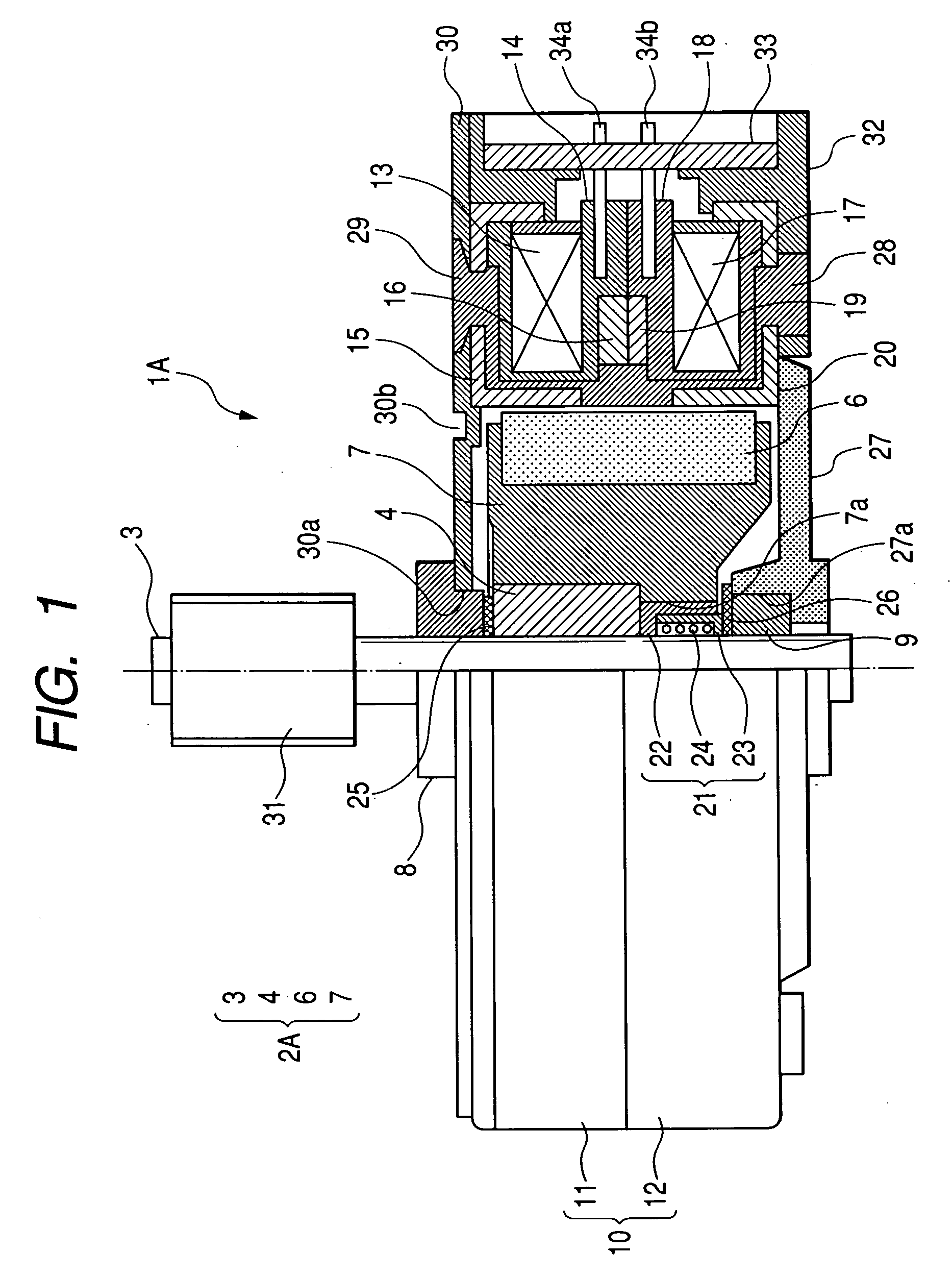
[0021] Referring to FIG. 1, a stepping motor, specifically a PM stepping motor 1A according to the present invention comprises a rotor assembly 2A rotatably supported, and a stator assembly 10 to surround the rotor assembly 2A.

[0022] The rotor assembly 2A includes a rotary shaft 3, a sleeve 4 formed of a non-magnetic material, and a magnet 6 disposed outside the sleeve 4. The sleeve 4 and the magnet 6 are rigidly fixed together via a resin portion 7 formed therebetween by injection molding. The magnet 6 is shaped into a ring formed of ferrite or a rare earth material, and has multi-pole magnetization provided on its outer circumferential surface. The rotary shaft 3 is rotatably supported by a bearing 8 and a bearing 9. The bearings 8 and 9 may be made of a plastic material or a general metallic material, but most preferably of a lubrication oil-impregnated metal in view of maintenance and cost. The bearings 8 and 9 may alternatively be ball bearings.

[0023] The stator assembly 10 is...

second embodiment

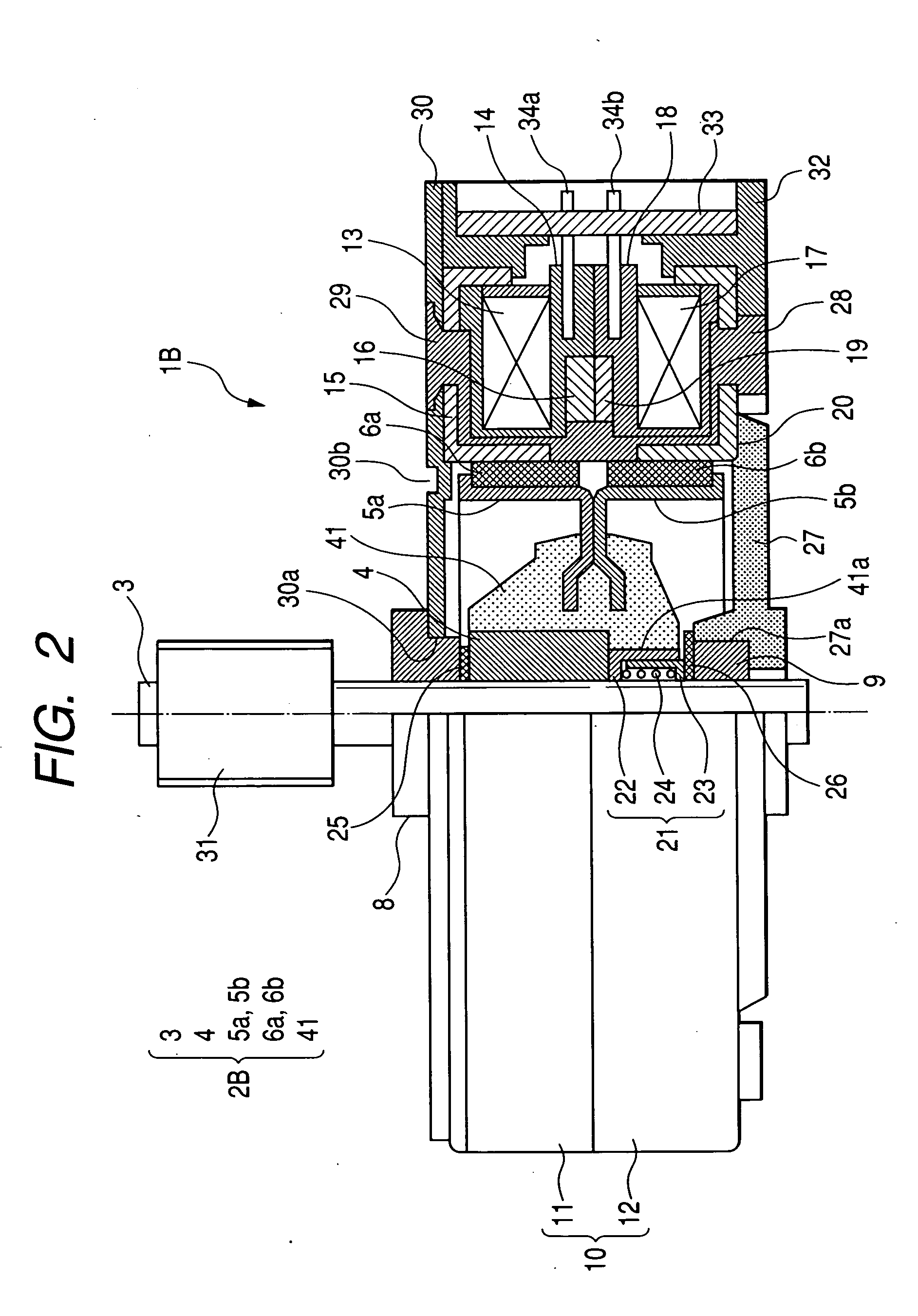
[0036] the present invention will hereinafter be described with reference to FIG. 2. A stepping motor 1B of FIG. 2 is basically identical with the stepping motor 1A of FIG. 1 except the structure of a rotor assembly 2B, and in explaining FIG. 2, any component parts identical with those in FIG. 1 are denoted by the same reference numerals.

[0037] The rotor assembly 2B of the stepping motor 1B includes a rotary shaft 3, a sleeve 4, a pair of back yokes 5a and 5b each having a substantially L-letter cross-sectional configuration, and two magnets 6a and 6b each shaped into a ring, each having a multi-pole magnetization provided on its outer circumferential surface, and fixedly attached to the outsides of the back yokes 5a and 5b. The sleeve 4 and the back yokes 5a and 5b are rigidly fixed together via a resin portion 41 formed therebetween. The rotary shaft 3 is rotatably supported by a bearing 8 and a bearing 9.

[0038] The rotor assembly 2B is fabricated as follows.

[0039] The sleeve 4 ...


PUM


Abstract

There is provided a stepping motor comprising: a stator assembly; a rotor assembly rotatably disposed inside the stator assembly, and including a rotary shaft rotatably supported by bearings, a sleeve fixedly attached onto the rotary shaft, and at least one magnet disposed outside the sleeve; and a preloading mechanism disposed between the sleeve and one of the bearings, and including a coil spring, and a spring holder which is composed of an outer case shaped in a cup-like configuration and an inner case shaped in a cup-like configuration, and which is adapted to house the coil spring. In the stepping motor described above, the spring holder of the preloading mechanism is formed of reinforced polyamide resin, and a washer member having a high sliladability is disposed between the preloading mechanism and the one bearing.

Description

BACKGROUND OF THE INVENTION [0001] 1. Field of the Invention [0002] The present invention relates to a stepping motor, and more particularly to a stepping motor which is used in high-temperature environments and / or frictional heat generating environments therefore requiring heat resistance performance. [0003] 2. Description of the Related Art [0004] Stepping motors, which are conveniently and well controllable, are used in various audio visual and office automation equipments. Especially, permanent magnet (PM) stepping motors are extensively used also in various control equipments carried in a vehicle due to low cost. Among the control equipments, for example, a following-distance sensor, and a headlamp optical axis controller are known. In a following-distance sensor, in which an ultrasonic sound wave is projected onto a preceding vehicle, and a reflected wave from the preceding vehicle is received for measuring a distance from the preceding vehicle, a crankshaft is attached to a r...

Claims


Application Information

Patent Timeline
Patent Type & Authority Applications(United States)
IPC IPC(8): H02K1/28H02K5/167H02K37/14H02K37/22
CPCH02K1/28H02K37/22H02K37/14H02K5/1672
Inventor HATA, MASATOSUZUKI, YAUZURUFUKUSHIMA, ATSUSHIHARADA, NAOYUKI
Owner MINEBEAMITSUMI INC
Why Eureka
Try Eureka