Spark plug

a technology of spark plugs and plugs, which is applied in the direction of spark plugs, machines/engines, mechanical equipment, etc., can solve the problems of reducing the thermal capacity of ground electrodes and insufficient heat-resistance properties of ground electrodes

Active Publication Date: 2005-12-01
DENSO CORP
View PDF1 Cites 13 Cited by
  • Summary
  • Abstract
  • Description
  • Claims
  • Application Information

AI Technical Summary

Benefits of technology

[0006] In general, improvement of ignitability depends on growth of the flame kernel formed after spark discharge. However, if the mixture flow velocity is fast, the flame kernel will be shifted toward a ground electrode and will be brought into contact with the ground electrode. As soon as the flame kernel contacts with the ground electrode, the flame kernel loses its thermal energy. This phenomenon is referred to as quenching effects. The quenching effects lessen the ignitability.
[0007] To reduce quenching effects, it is effective to reduce the thickness of the ground electrode. However, reducing the thickness of the ground electrode will reduce the thermal capacity of the ground electrode. Accordingly, the ground electrode will have insufficient heat-resisting properties.

Problems solved by technology

However, reducing the thickness of the ground electrode will reduce the thermal capacity of the ground electrode.
Accordingly, the ground electrode will have insufficient heat-resisting properties.

Method used


Image

  • Spark plug
  • Spark plug
  • Spark plug

Examples


first embodiment

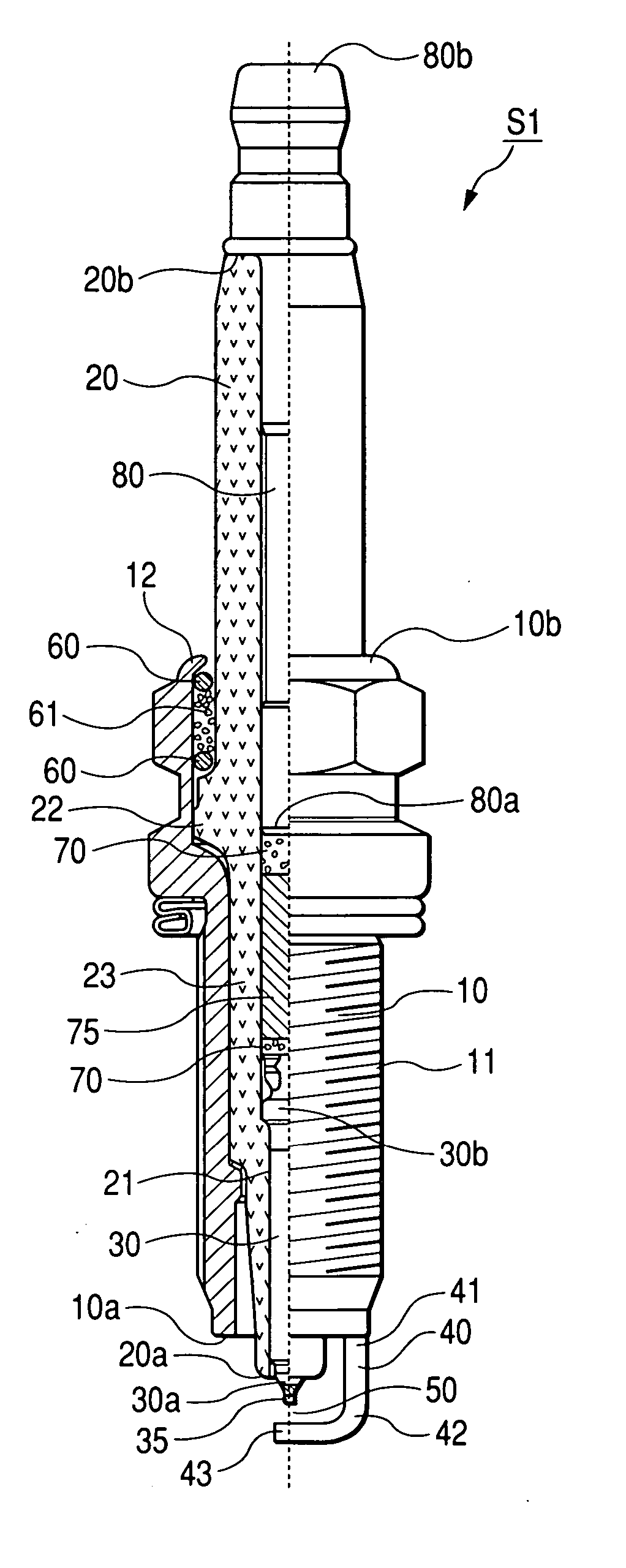
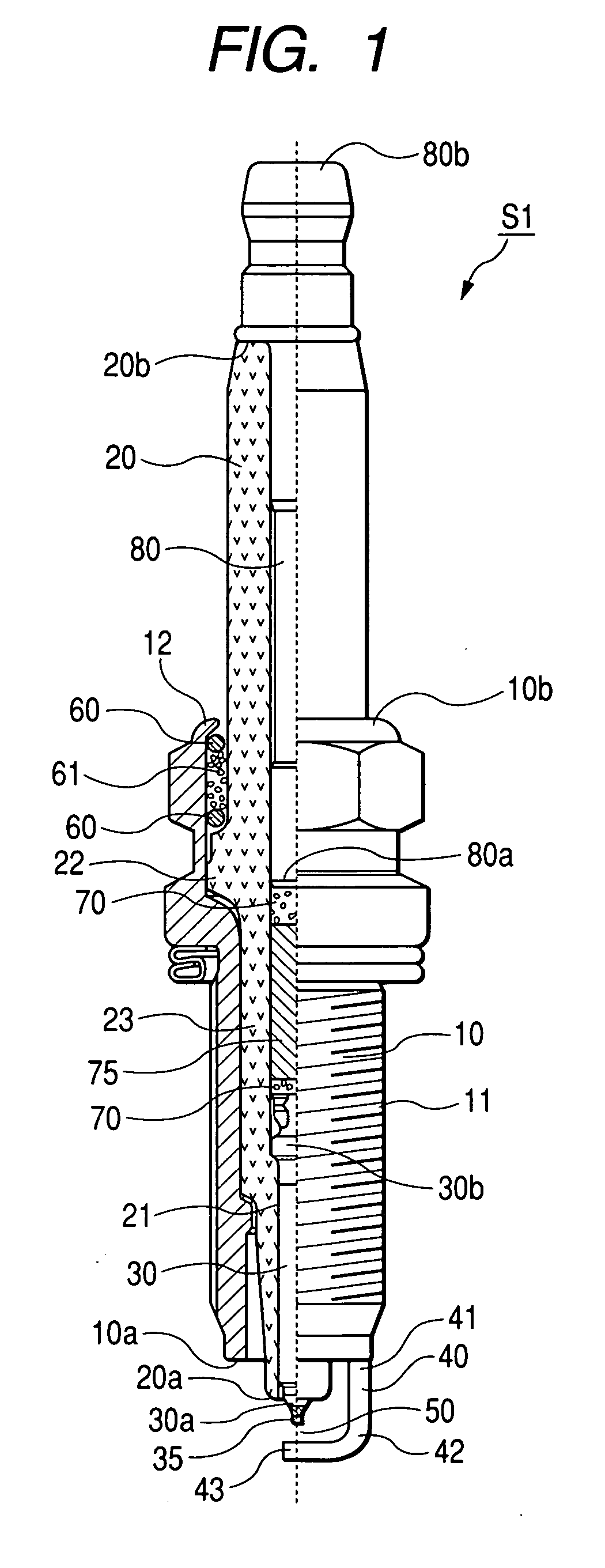
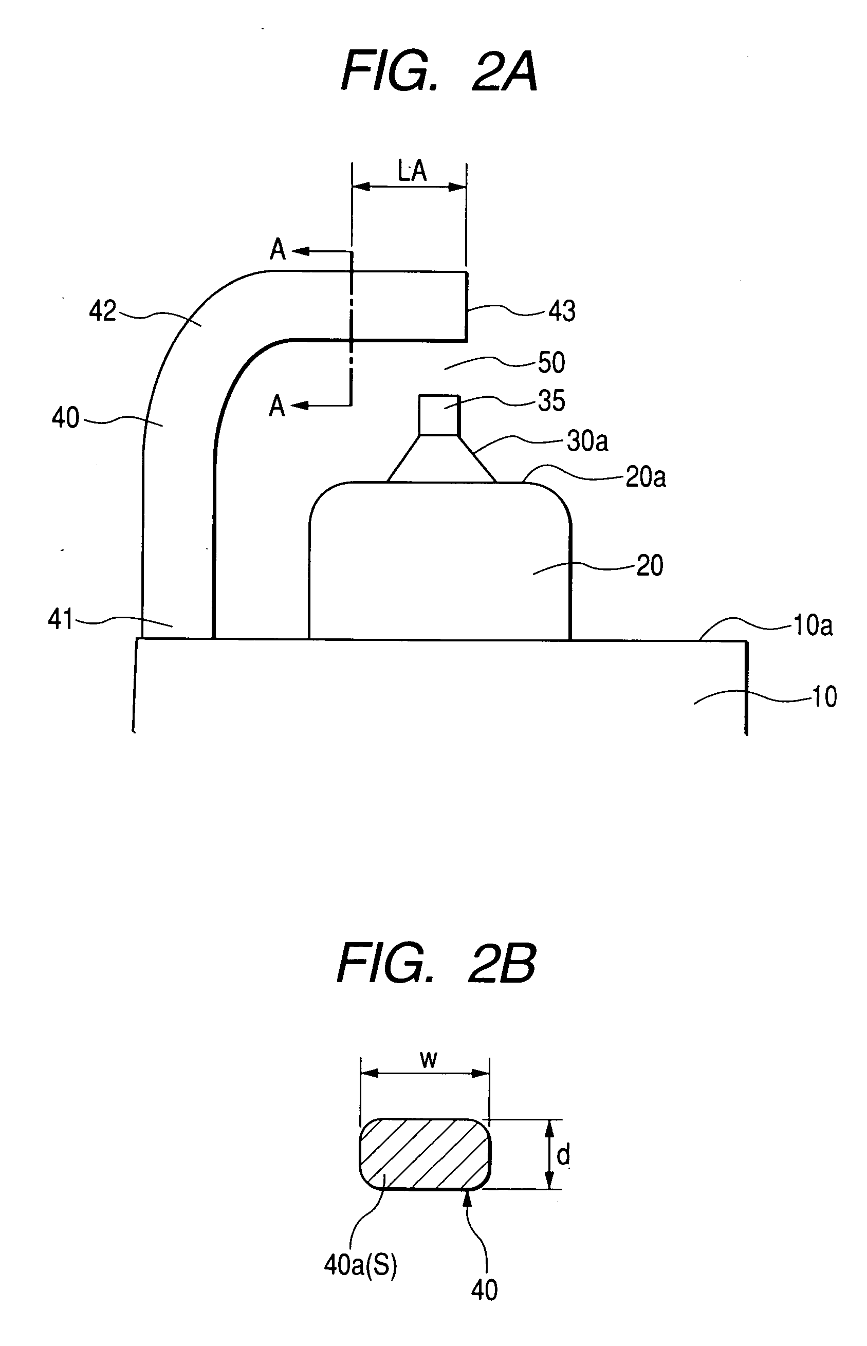
[0062]FIG. 1 is a half cross-sectional view showing an overall arrangement of a spark plug S1 in accordance with a first embodiment of the present invention. FIG. 2A is an enlarged side view showing an igniting portion of the spark plug S1 shown in FIG. 1. FIG. 2B is a cross-sectional view showing the spark plug S1, taken along a line A-A of FIG. 2A.

Arrangement of Spark Plug

[0063] The spark plug S1 is preferably applicable to an automotive engine as an ignition plug which is inserted and fixed in a screw hole provided in an engine head (not shown) defining therein a combustion chamber.

[0064] The spark plug S1 includes a cylindrical metal housing 10 made of an electrically conductive steel plate (e.g. low-carbon steel). A fixing screw portion 11 is provided on an outer cylindrical surface of the metal housing 10, so that the metal housing 10 can be fixed to an engine block (not shown). According to this embodiment, the fixing screw portion 11 is M10 or less according to JIS (i.e. ...

second embodiment

[0136] A spark plug in accordance with a second embodiment of the present invention will be explained with reference to the drawings used for explaining the first embodiment. Hereinafter, differences between the first and second embodiments will be explained in detail.

[0137] The spark plug of the second embodiment includes the metal housing 10 having the fixing screw portion 11 provided on the outer surface thereof so as to be installed to an engine via the fixing screw portion 11. The insulator 20, fixed in the metal housing 10, has one end portion 20a protruding from one end portion 10a of the metal housing 10. The center electrode 30, fixed in an axial hole 21 of the insulator 20, has one end portion 30a protruding from one end portion 20a of the insulator 20. The ground electrode 40 has one end portion 41 fixed to the metal housing 10, the bent portion 42 provided at the intermediate portion thereof, and the other end portion 43 positioned in a confronting relationship with one...

third embodiment

[0155] A spark plug in accordance with a third embodiment of the present invention will be explained with reference to the drawings used for explaining the first embodiment. Hereinafter, differences between the first and third embodiments will be explained in detail.

[0156] The spark plug of the third embodiment includes the metal housing 10 having the fixing screw portion 11 provided on the outer surface thereof so as to be installed to an engine via the fixing screw portion 11. The insulator 20, fixed in the metal housing 10, has one end portion 20a protruding from one end portion 10a of the metal housing 10. The center electrode 30, fixed in an axial hole 21 of the insulator 20, has one end portion 30a protruding from one end portion 20a of the insulator 20. The ground electrode 40 has one end portion 41 fixed to the metal housing 10, the bent portion 42 provided at the intermediate portion thereof, and the other end portion 43 positioned in a confronting relationship with one en...


PUM


Abstract

A ground electrode has one end portion fixed to a metal housing, a bent portion provided at an intermediate portion thereof, and the other end portion positioned in a confronting relationship with a center electrode to form a spark discharge gap. The ground electrode contains either Ni or Fe as a main component and at least one additive selected from the group consisting of Cr and Al. A cross-sectional area S of the ground electrode is not less than 2 mm2 and not greater than 3 mm2. An average value D of crystal grain diameters in a thickness direction is not less than 100 μm at least at the bent portion.

Description

CROSS-REFERENCE TO RELATED APPLICATION [0001] This application is based upon and claims the benefit of priority from earlier Japanese Patent Application No. 2004-154388 filed on May 25, 2004 so that the description of which is incorporated herein by reference. BACKGROUND OF THE INVENTION [0002] The present invention relates to a spark plug for an internal combustion engine. [0003] In general, a spark plug includes a metal housing having a fixing screw portion provided on an outer surface thereof so as to be installed to an engine via this fixing screw portion. An insulator, fixed in the metal housing, has one end portion protruding from one end portion of the metal housing. A center electrode, fixed in an axial hole of the insulator, has one end portion protruding from one end portion of the insulator. A ground electrode has one end portion fixed to the metal housing, a bent portion provided at an intermediate portion thereof, and the other end portion positioned in a confronting re...

Claims


Application Information

Patent Timeline
Patent Type & Authority Applications(United States)
IPC IPC(8): H01T13/39H01T13/20H01T13/32
CPCH01T13/32
Inventor KANAO, KEIJI
Owner DENSO CORP
Why Eureka
Try Eureka