Electronic lock system and method for its use with a secure memory card

a technology of electronic locks and memory cards, applied in the field of electronic locks, can solve the problems of inapplicability, inability to address the fundamental problem of conventional locks, and inability to meet the requirements of electronic keys,

Inactive Publication Date: 2005-12-01
SENTRILOCK
View PDF61 Cites 52 Cited by
  • Summary
  • Abstract
  • Description
  • Claims
  • Application Information

AI Technical Summary

Benefits of technology

[0009] Accordingly, it is an advantage of the present invention to provide a lock box 
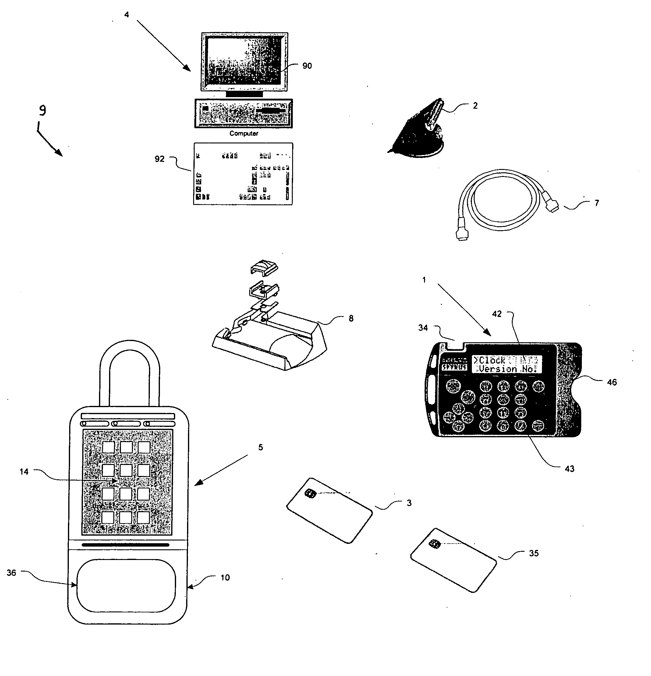
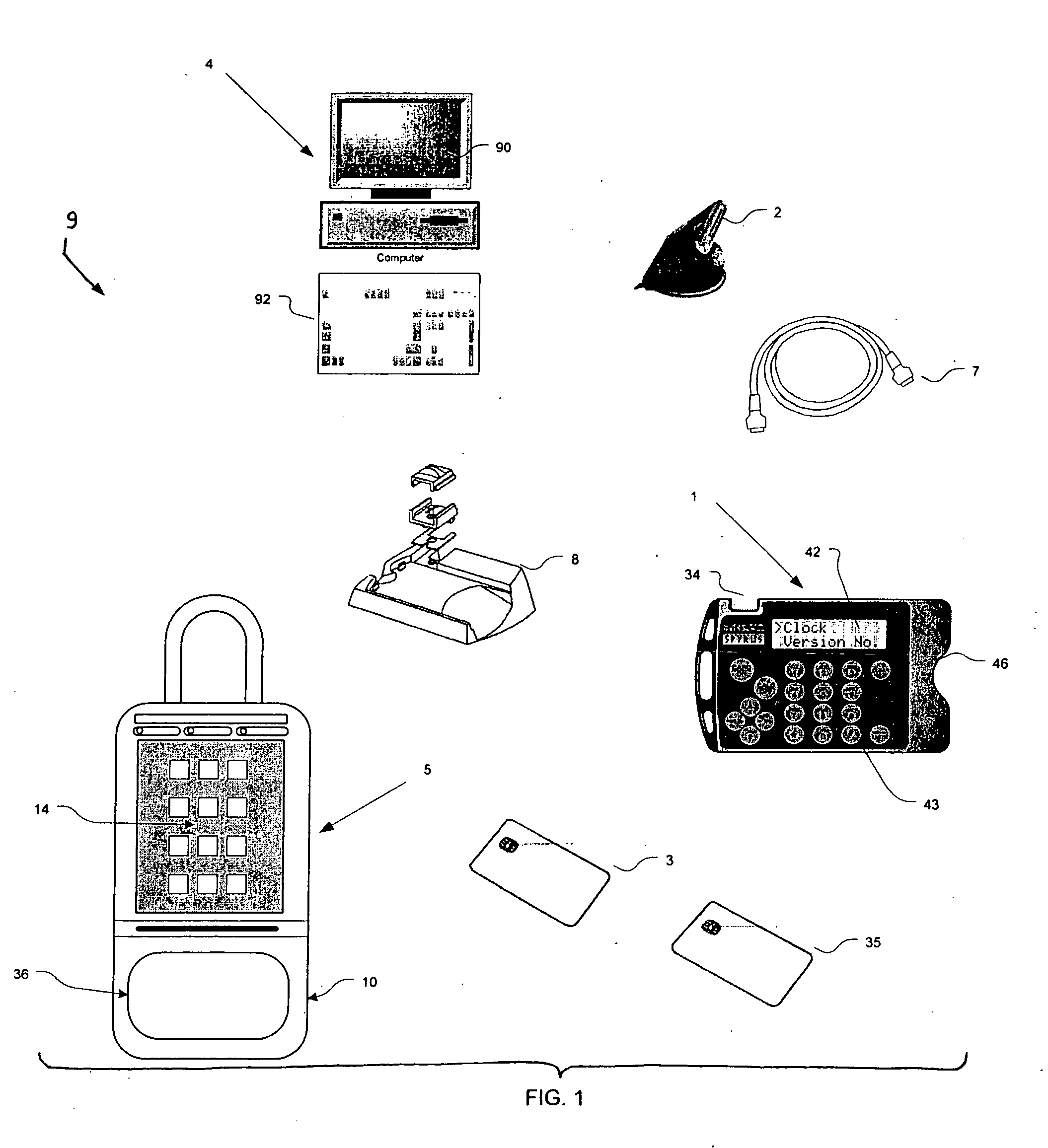
system used in real estate sales systems in which the user carries a very small portable computer and a credit card-sized memory card that interfaces both to the portable computer and to a lock box. The lock box itself generates the access code as a random number, which the user can learn only by entering correct information on the portable computer after the portable computer reads data stored on the memory card after the memory card has interacted with the lock box electronics. The user manually enters the access code on a keypad of the lock box to obtain access to the key compartment.
[0010] It is another advantage of the present invention to provide a lock box system used in real estate sales systems in which the user carries a mobile telephone (or other communications device) and a credit card-sized memory card, in which the user receives an access code from a central “clearinghouse computer,” and in which the access code periodically changes over time using an algorithm know both to the lock box and to the clearinghouse computer. The user manually enters the access code on a keypad of the lock box to obtain access to the key compartment.
[0011] It is a further advantage of the present invention to provide a lock box system used in real estate sales systems which has many different optional features, such as a “showing by appointment” feature that requires a special access code, and the ability to display special showing instructions.
[0012] It is yet another advantage of the present invention to provide a lock box system used in real estate sales systems in which the user carries only a credit card-sized memory card, and in which the user receives an access code from a central “clearinghouse computer,” or from a regional “office computer.” The access code periodically changes over time using an algorithm known both to the lock box and to the clearinghouse computer, and the “epoch time” is divided into time intervals (“window intervals” or “window interval periods”) that themselves are used to help create “interval dividend numbers” or “window interval dividends” or “code life interval dividend” numeric values. The user manually enters the access code on a keypad of the lock box to obtain access to the key compartment, or to unlock a shackle holding the lock box to a fixed object. Alternatively, the data resident on the portable memory card is directly transferred to the lock box computer, and this data allows automatic access to the key compartment, or it automatically unlocks the shackle.
[0013] Additional advantages and other novel features of the invention will be set forth in part in the description that follows and in part will become apparent to those skilled in the art upon examination of the following or may be learned with the practice of the invention.
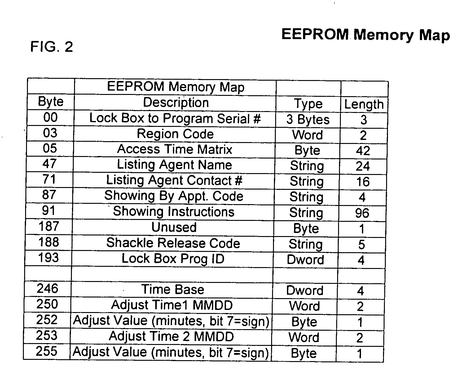
[0014] To achieve the foregoing and other advantages, and in accordance with one aspect of the present invention, a method for operating an electronic lock box system is provided, in which the method comprises the steps of: (a) providing an electronic lock box having a compartment with a controlled access member, a first memory circuit for storage of data, a first keypad, a first communications port, and a first processing circuit; (b) providing a portable computer having a second memory circuit for storage of data, a second keypad, a display, a second communications port, and a second processing circuit; (c) providing a portable memory device containing a non-volatile third memory circuit; (d) coupling the portable memory device to the first communications port of the electronic lock box so as to permit communications therebetween, and loading access code information from the first memory circuit to the third memory circuit; (e) uncoupling the portable memory device from the first communications port of the electronic lock box; (f) coupling the portable memory device to the second communications port of the portable computer so as to permit communications therebetween, and reading the access code information from the third memory circuit to the second memory circuit; (g) entering identification information using the second keypad, and if the identification information is correct as determined by the portable computer, displaying the access code information on the display to a human user; and (h) entering the access code information using the first keypad, and if the access code information is correct as determined by the first processing circuit, releasing the controlled access member of the compartment.

Problems solved by technology

The greatest challenge in previous designs has been the management and updating of electronic keys and electronic lock boxes with current access code information.
This has not been a huge problem from the key side with the advent of central computer systems communicating with keys; however, conventional systems now in use have not addressed the fundamental problem of updating lock box devices that are dispersed over a large geographic area.
The previous designs and prior art patent literature provide an updating function via a radio signal or a pager, however, these systems are impractical due to the receiving circuit's power drain and potential proximity constraints with respect to the physical locations of receiver and transmitter.
In fact, these prior art systems have increasingly encompassed more costly and cumbersome electronic key solutions that are required to be periodically updated with new access codes.

Method used


Image

  • Electronic lock system and method for its use with a secure memory card
  • Electronic lock system and method for its use with a secure memory card
  • Electronic lock system and method for its use with a secure memory card

Examples


Embodiment Construction

[0054] Reference will now be made in detail to the present preferred embodiment of the invention, an example of which is illustrated in the accompanying drawings, wherein like numerals indicate the same elements throughout the views.

[0055] The present invention supports two distinct lock box access methodologies. The first methodology uses a system of conditional access code that are disclosed to the user for controlling lock box key compartment access. The access code is conveyed securely from the lock box to a portable computer via a secure memory device (also referred to as a “secure memory card”); moreover, the access code is generated as a random number (by the lock box) and is generated in real time as the attempted access is in progress. Depending on expiration status and other factors, the portable computer determines whether the lock box access code should be revealed to the user.

[0056] The main security aspect of the system (of this first methodology) relies upon randoml...


PUM


Abstract

An improved electronic lock system is provided for use with real estate lock boxes. Each user has an identification card with a non-volatile secure memory for exchanging data with the lock box, and for exchanging data with a central computer. The user first inserts the card into a connector at the lock box, or at the central computer. The lock box or central computer must first enable (or unlock) the data in the card memory, and then can read the data stored in that card's memory and record this information in lock box memory. The card must then identify itself, and the user must identify himself/herself to the lock box or central computer. After the identification information is authenticated, the user can enter commands to the lock box; e.g., an access code is manually keyed into the lock box keypad by the user to obtain access to a secure compartment.

Description

CROSS-REFERENCE TO RELATED APPLICATIONS [0001] The present application is a continuation of application Ser. No. 10 / 267,174, titled “ELECTRONIC LOCK SYSTEM AND METHOD FOR ITS USE WITH CARD ONLY MODE,” filed on Oct. 9, 2002; which is a continuation-in-part of application Ser. No. 10 / 172,316, titled “ELECTRONIC LOCK SYSTEM AND METHOD FOR ITS USE,” filed on Jun. 14, 2002.TECHNICAL FIELD [0002] The present invention relates generally to electronic lock systems and is particularly directed to real estate lock box systems that provide an improvement in access code management. The invention is specifically disclosed as a lock box access system that uses a “smart card” with on-board non-volatile memory that receives a randomly-generated access code from a lock box, and in which that random access code is readable by a credit-card sized portable computer that first determines if the user is authorized to have access to the lock box before displaying the access code to the user. In an alterna...

Claims


Application Information

Patent Timeline
Patent Type & Authority Applications(United States)
IPC IPC(8): E05B47/00G05B19/00G06F19/00G07C9/00
CPCE05B19/0005G07C9/00103G07C9/00571G07C9/0069G07C9/00896G07C2209/62G07C2009/00388G07C2009/00476G07C2009/00761G07C2209/08G07C9/00912Y10T70/5031G07C9/27
Inventor FISHER, SCOTT R.
Owner SENTRILOCK
Why Eureka
Try Eureka