Nerve stimulator and method

a nerve stimulator and electrode technology, applied in the field of nerve stimulator, can solve the problems of unpredictable development of voltage gradients for depolarization, and achieve the effect of improving nerve localization

Inactive Publication Date: 2005-12-01
NERVONIX INC
View PDF37 Cites 67 Cited by
  • Summary
  • Abstract
  • Description
  • Claims
  • Application Information

AI Technical Summary

Benefits of technology

[0023] This invention provides several objectives and advantages. First, it provides a means of developing a predictable voltage gradient across the neuronal cell membrane. Second, the invention provides a means of maintaining the voltage output despite changes in load. Third, the invention provides a means for delivering an adequate pulse duration for neuronal cell depolarization. Fourth, the invention provides a means for the determination of tissue electrical parameters. Fifth, the invention provides a means for adjusting output characteristics based on measured tissue electrical parameters. The principal advantage of a system satisfying these objects is improved localization of nerves or nerve plexuses for regional anesthesia, pain management, and other medical purposes.

Problems solved by technology

However, there are several problems with these devices.
Since the impedance decreases as the needle tip approaches the nerve, the applied voltage will also decrease, making the development of an adequate voltage gradient for depolarization unpredictable.

Method used


Image

  • Nerve stimulator and method
  • Nerve stimulator and method
  • Nerve stimulator and method

Examples


Embodiment Construction

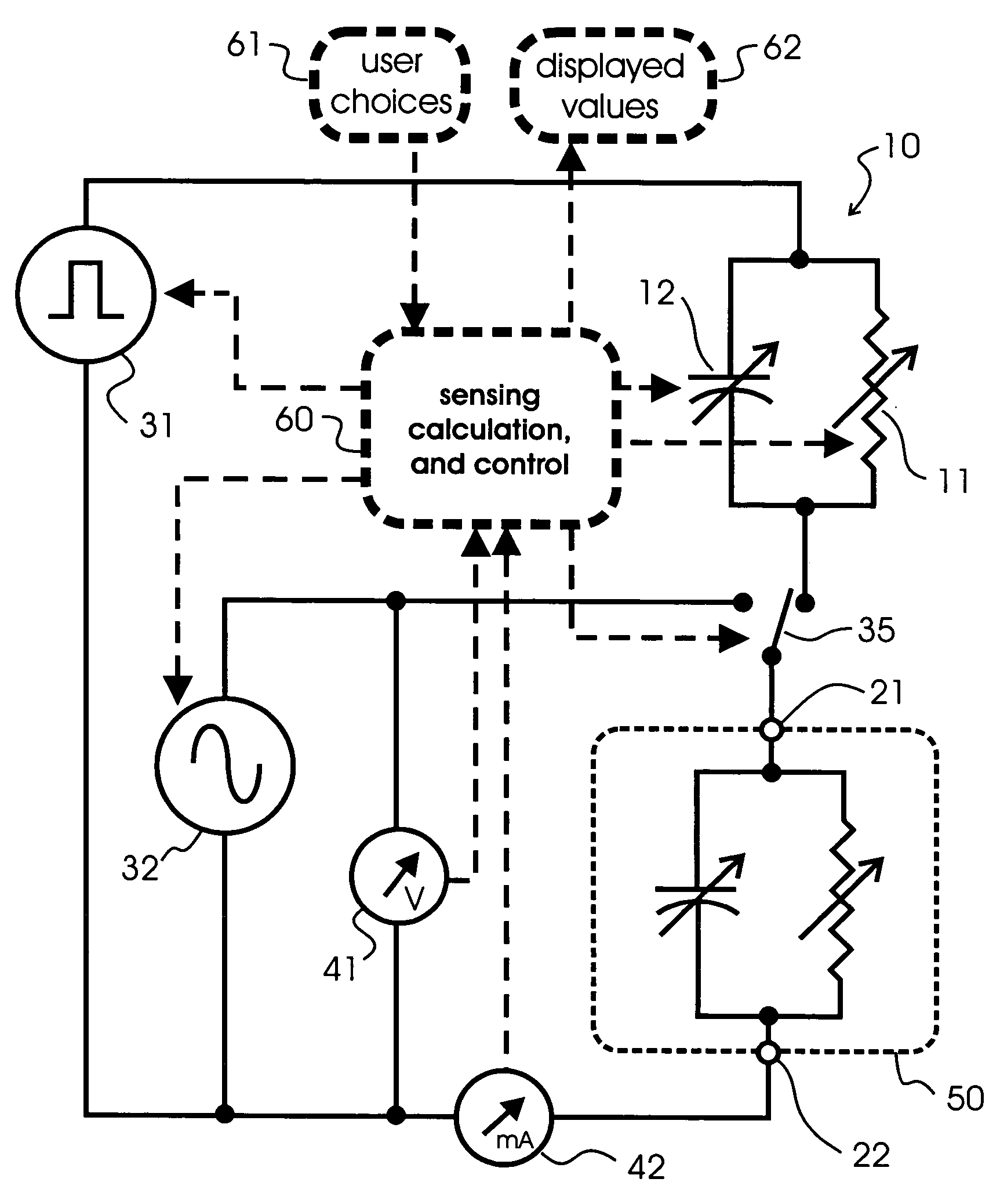
[0034] A description of the preferred embodiment and some variations will make reference to the schematic diagram in FIG. 3. The solid lines represent electronic circuitry. The dotted box 50 represents the nerve-containing tissue and encloses an equivalent resistance and capacitance between the needle electrode 21 and the return electrode 22. The tissue resistance and capacitance vary, as the needle is advanced through the tissue-presumably toward a nerve.

[0035] The circuitry comprises two waveform generators 31 and 32, a pulse conditioning circuit 10 with a variable resistor 11 and a variable capacitor 12, a switch 35 which connects one of the two generators at a time into the circuitry, a percutaneous needle electrode 21, a ground electrode 22, and sensors 41 and 42 to measure electrical characteristics such as instantaneous voltage and current between the electrodes in real time. Resistor-capacitor (RC) circuit 50 represents the effective electrical characteristics of the tissue...


PUM


Abstract

This invention presents a device, and the method it implements, which is an improvement in the design of nerve stimulators. Like conventional stimulators, it uses a percutaneous, insulated needle for the performance of therapeutic interventions targeting nerves. The improvement comprises offering an option for either constant current or constant voltage, offering a choice of waveform parameters, controlling a pulse generator, supplying a second background waveform, measuring the current and voltage applied to the tissue, computing further electrical characteristics, dynamically adjusting circuit components to ensure a desirable waveform applied to the tissue, and displaying measured and computed electrical characteristics of the tissue. The object is improved positioning of a needle tip near a nerve or nerve plexus for regional anesthesia, pain management, and other medical purposes.

Description

FIELD OF INVENTION [0001] This invention relates to the stimulation of nerves with invasive electrodes for targeted therapeutic interventions. BACKGROUND [0002] Nerve stimulators commercially available for targeted nerve therapies are exemplified by the NeuroTrace III (HDC Corp., Milpitas, Calif.), the Stimuplex (B.Braun America, Bethlehem, Pa.) and the Digistim III (NeuroTechnologies, Inc, Chennai, India), among others. These devices are constant current, monophasic, pulsed square waveform generators having pulse widths no longer than 200 microseconds in duration. These devices are connected to insulated hypodermic needles which are inserted through the skin and advanced toward the presumed position of a target nerve. Accurate localization of the needle tip is presumed when either a sensory paresthesia or a motor paresthesia is provoked by current outputs less than 0.5 mA. This work is derived from historical strength-duration curves. However, there are several problems with these ...

Claims


Application Information

Patent Timeline
Patent Type & Authority Applications(United States)
IPC IPC(8): A61B5/053A61N1/18A61N1/34
CPCA61B5/053A61N1/36021A61N1/36017A61B5/4041
Inventor CORY, PHILIP C.
Owner NERVONIX INC
Why Eureka
Try Eureka