Vibration damping device and bucket for construction machine

Inactive Publication Date: 2005-12-08
KOMATSU LTD
View PDF39 Cites 5 Cited by
  • Summary
  • Abstract
  • Description
  • Claims
  • Application Information

AI Technical Summary

Benefits of technology

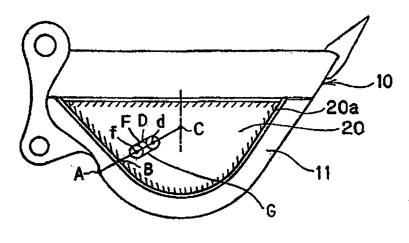
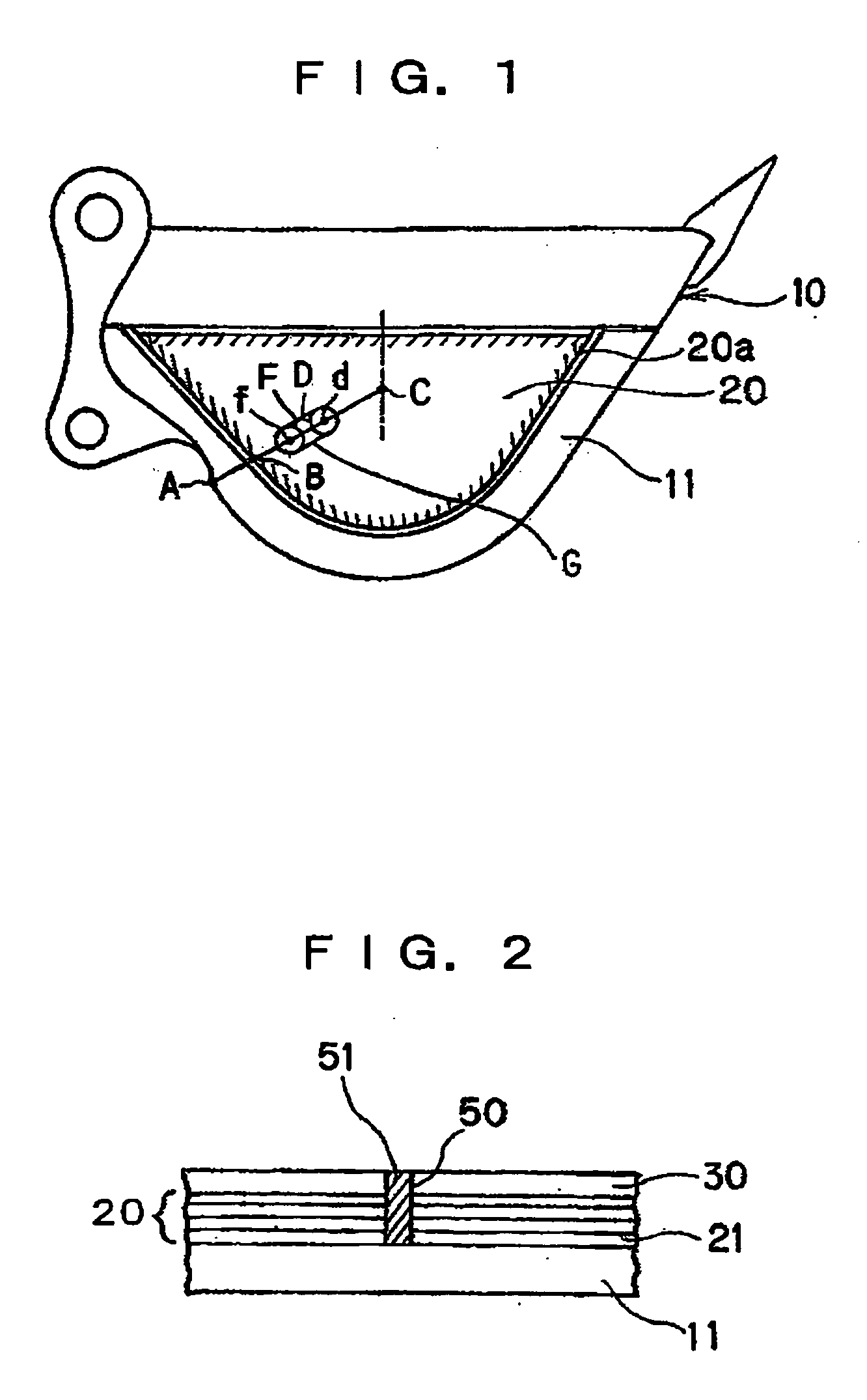
[0028] The present invention was devised in order to solve such problems encountered in the prior art; it is an object of the present invention to provide a vibration damping device in which a high vibration damping effect can be maintained by fastening appropriate parts in the interior part of the laminated plate so that there is no loss of the vibration damping effect due to thermal strain during manufacture or the occurrence of “floating” caused by external forces during use, and so that there is no interference with the independent deformation of the thin plates that make up the laminated plate. Furthermore, it is an object of the present invention to provide a bucket for a construction machine which is devised so that noise countermeasures can be taken with the minimum required effort, without performing noise experiments or the like on the bucket, and which makes it possible to reinforce the bottom plate of the bucket with the minimum required increase in weight. Moreover, it is an object of the present invention to provide a vibration damping device which is superior in terms of vibration damping performance, and which can prevent the generation of noise in the internal portions.

Problems solved by technology

For example, in the case of hydraulic excavators equipped with work equipment including buckets, it has been confirmed by experiment that such buckets are the main source of noise.
It has been claimed that approximately 80% of the noise emitted from such work equipment is noise emitted from buckets.
However, construction machinery is commonly used to perform work under harsh conditions, with the work equipment exposed to earth, sand and the like, and if vibration damping materials consisting of viscoelastic materials are attached to the work equipment, the problem of insufficient durability arises.
Furthermore, such viscoelastic materials are generally constrained by metal plates, and in cases where these metal plates are repaired by welding, the problem of burning of the viscoelastic materials also arises.
Since such viscoelastic materials are expensive, the problem of high cost of noise countermeasures also arises.
However, it has become clear that the following problems arise if the interior parts of the laminated plate 20 are not fastened.
Secondly, during actual work performed by construction machinery, excessively large external forces are commonly applied to the side plate 11 as a result of the bucket striking rocks and the like.
However, if the internal portions of the laminated plate 20 are not fastened, “floating” occurs as a result of thermal strain during the manufacture of the bucket and external forces during the use of the bucket, so that the problem of a loss of the vibration damping effect arises.
However, in cases where the method of the abovementioned (1) is adopted, noise experiments and the like must be performed each time that a bucket is newly designed, which involves considerable trouble.
Furthermore, in cases where the method of the abovementioned (2) is adopted, it is necessary to add parts used for noise countermeasures even in the case of buckets that do not require noise countermeasures, so that the cost is increased.
On the other hand, in cases where noise counter measures are performed on the bottom plates of buckets, there are instances in which laminated plate cannot be attached (unlike the case of the side plate).
Specifically, during the work performed by construction machinery, the bottom plate of the bucket often has occasion to strike rocks or the like; accordingly, compared to the side plate, the bottom plate is more frequently subjected to excessive external forces, so that the bottom plate is subjected to severe wear.
Accordingly, there is a danger that laminated plate attached to the bottom plate will be destroyed or separated, and is therefore deficient in durability.
Furthermore, in cases where laminated plate is attached to the bottom plate, the problem of increased cost also arises.
However, increasing the thickness of the wear plate leads to an increase in the weight of the bucket, and thus has a deleterious effect on the performance of the construction machinery.
When the counter-weight is increased, the problem of an increase in the turning radius of the construction machinery arises.
However, in the case of such conventional techniques, problems such as those described below arise.
Specifically, in cases where such techniques are applied to the side plate of the bucket in a hydraulic excavator, if bolt fastening or plug welding is used for the partial coupling of the side plate and laminated plate, rain water enters via the end surfaces of the laminated plate so that rusting occurs between the plates, thus causing a drop in the vibration damping performance.
If all round welding of the end surfaces of the laminated plate is used for the partial coupling of the side plate and laminated plate in order to prevent rusting, the plates forming the laminated plate are mutually constrained, so that the generation of very small positional deviations and the like is impeded, thus causing a drop in the vibration damping performance.
However, the following problems are encountered even in cases where the abovementioned wear plate 108 is used.
(3) Since the volume of the welded parts is large, the cost increases with the amount of work that is required.
(4) In order to prevent floating and deformation caused by thermal strain during continuous welding, it is necessary to effect a temporary attachment of the laminated plate 150 and side plate 103 at an extremely large number of points, so that considerable work is required, and the cost is increased.

Method used


Image

  • Vibration damping device and bucket for construction machine
  • Vibration damping device and bucket for construction machine
  • Vibration damping device and bucket for construction machine

Examples


example 1

[0111] Connecting members 15 are attached over the entire region of the corner parts 16.

example 2

[0112] The main sources of the generation of the noise that is emitted from the bottom plate 12 are specified, and connecting members 15 are attached in these parts only. When the frequency spectrum of the noise occurring during actual work performed by the construction machine was analyzed, it was found that it is important to reduce noise in the frequency bands in which large peaks are generated. Accordingly, vibration modal analysis of the bucket 10 is performed at frequencies in the frequency bands in which large peaks are generated, and the main sources of the noise that is emitted from the bottom plate 12 are located. FIG. 10 shows a typical vibration mode amplitude distribution for the bucket 10; the respective parts are indicated by light or dark shades according to the size of the amplitude. Furthermore, in FIG. 10, the attachment positions of the tooth 18 and bracket 19 are indicated in order to clarify the correspondence with FIG. 6.

[0113] As is shown in FIG. 10, the siz...

example 3

[0114] Connecting members 15 are attached in a configuration in which the ratio Wp′ / Hs of the substantial width Wp′ of the bottom plate 12 to the height Hs of the side plate 11 is smaller than 1.47. As is shown in FIGS. 8A and 8B, connecting members 15 are respectively attached to both corner parts 16 of the bottom plate 12, and the length of a line segment that connects the connection parts 12a of the connecting members 15 is designated as the “substantial bottom plate width Wp′”. Here, as is shown in FIG. 9, it is assumed that the value of the ratio Wp / Hs prior to the attachment of the connecting members 15 is J2, and that this is in the region Q where the noise contribution T2 of the bottom plate 12 is the dominant factor. Connecting members 15 are attached in the region Q so that the reduction of the noise emitted from the bottom plate 12 is most efficient in reducing the noise of the bucket 10.

[0115] If connecting members 15 are attached, the ratio Wp′ / Hs can be altered from a...


PUM


Abstract

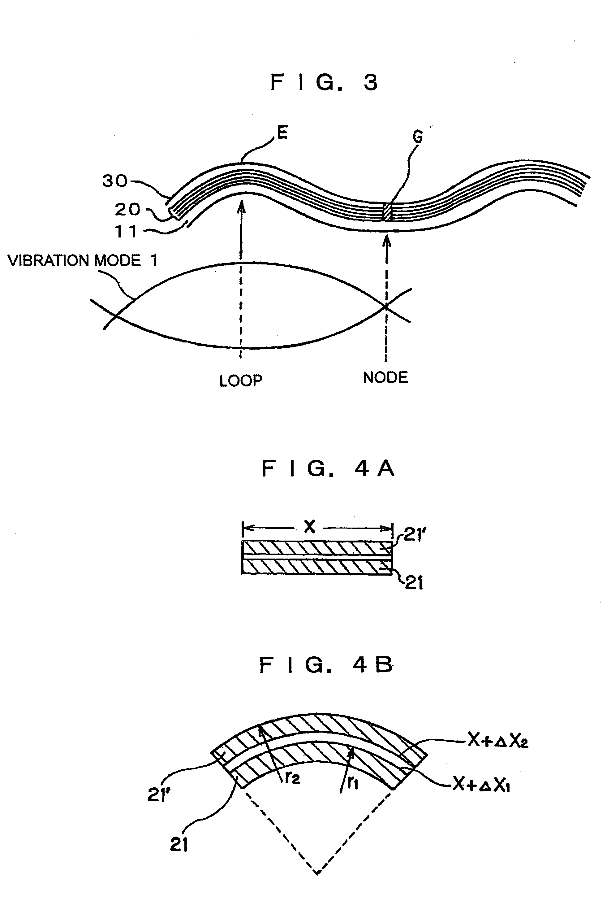
The invention provides a vibration damping device capable of maintaining high vibration damping effect, and a bucket for a construction machine. To this end, the vibration damping device has a laminated plate (20) having at least its inner region fixed in a noise-emitting base material (11), the inner region being a region (G) other then a region which becomes a loop in a vibration mode when the base material (11) is vibrated in a vibration mode with a predetermined frequency.

Description

TECHNICAL FIELD [0001] The present invention relates to a vibration damping device which suppresses vibration generated by a base material so that noise emitted from the base material is reduced, and a bucket for a construction machine. BACKGROUND ART [0002] In recent years, low noise levels have been required in construction machinery, especially in the case of nighttime work and in residential areas, and legal noise regulations which restrict noise to fixed levels or lower have also been enacted in various countries. For example, in the case of hydraulic excavators equipped with work equipment including buckets, it has been confirmed by experiment that such buckets are the main source of noise. It has been claimed that approximately 80% of the noise emitted from such work equipment is noise emitted from buckets. [0003] Accordingly, attempts have been made to attach vibration damping materials to buckets in order to suppress the vibration that is generated in the buckets, especiall...

Claims


Application Information

Patent Timeline
IPC IPC(8): E02F3/40F16F15/02
CPCE02F3/40Y10S37/904F16F15/02
Inventor IMAMURA, KAZUYANAKADA, KUNIAKINAKAGAWA, TAIZOU
Owner KOMATSU LTD
Why Eureka
Try Eureka