Brain probe and method for manufacturing same

a brain probe and probe body technology, applied in the field of brain probes, can solve the problems of brittleness of brain probes, inability to enlarge the circumference of brain probes, and inability to individually insert brain probes when inserted deeply into the brain, and achieve the effect of higher reception sensitivity

Active Publication Date: 2012-07-24
TOHOKU MICROTEC +1
View PDF7 Cites 15 Cited by
  • Summary
  • Abstract
  • Description
  • Claims
  • Application Information

AI Technical Summary

Benefits of technology

[0026]In accordance with the present invention, it is possible to obtain an omnidirecitonal brain probe that can be inserted individually to the deep portions of the brain and can detect and output electric signals with higher reception sensitivity over the entire circumference, without a spread in sensitivity caused by orientation.

Problems solved by technology

A variety of drug treatment methods are used for treating the Parkinson disease, but the effect of the drug treatment methods is lost after a long time and side effects are sometimes demonstrated.
Thus, since the entire brain probe described in Non-Patent Document 1 is formed from a silicon substrate, the brain probe is brittle and cannot be inserted individually when inserted deeply into the brain, for example, to the basal ganglia.
Further, since the brain probe of the Non-Patent Document 1 is oriented by the frontal direction (normal direction) of the planes (front plane, rear plane), the electric signal from the frontal direction is received with better sensitivity than the electric signal from the horizontal direction and sufficient reception sensitivity cannot be obtained for the entire circumference of the brain probe.
Thus, the problem is that although the electrodes are disposed on both surfaces, electric signals from specific directions cannot be received with sufficient sensitivity.

Method used


Image

  • Brain probe and method for manufacturing same
  • Brain probe and method for manufacturing same
  • Brain probe and method for manufacturing same

Examples


Embodiment Construction

[0041]The embodiments of the present invention will be described below with reference to the appended drawings. However, the embodiments place no limitation on the technical scope of the present invention.

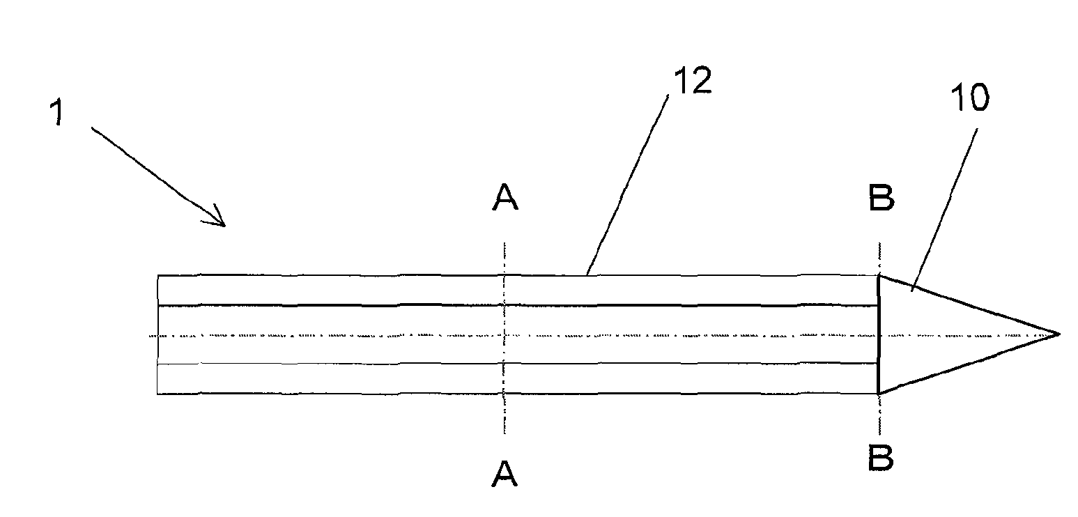
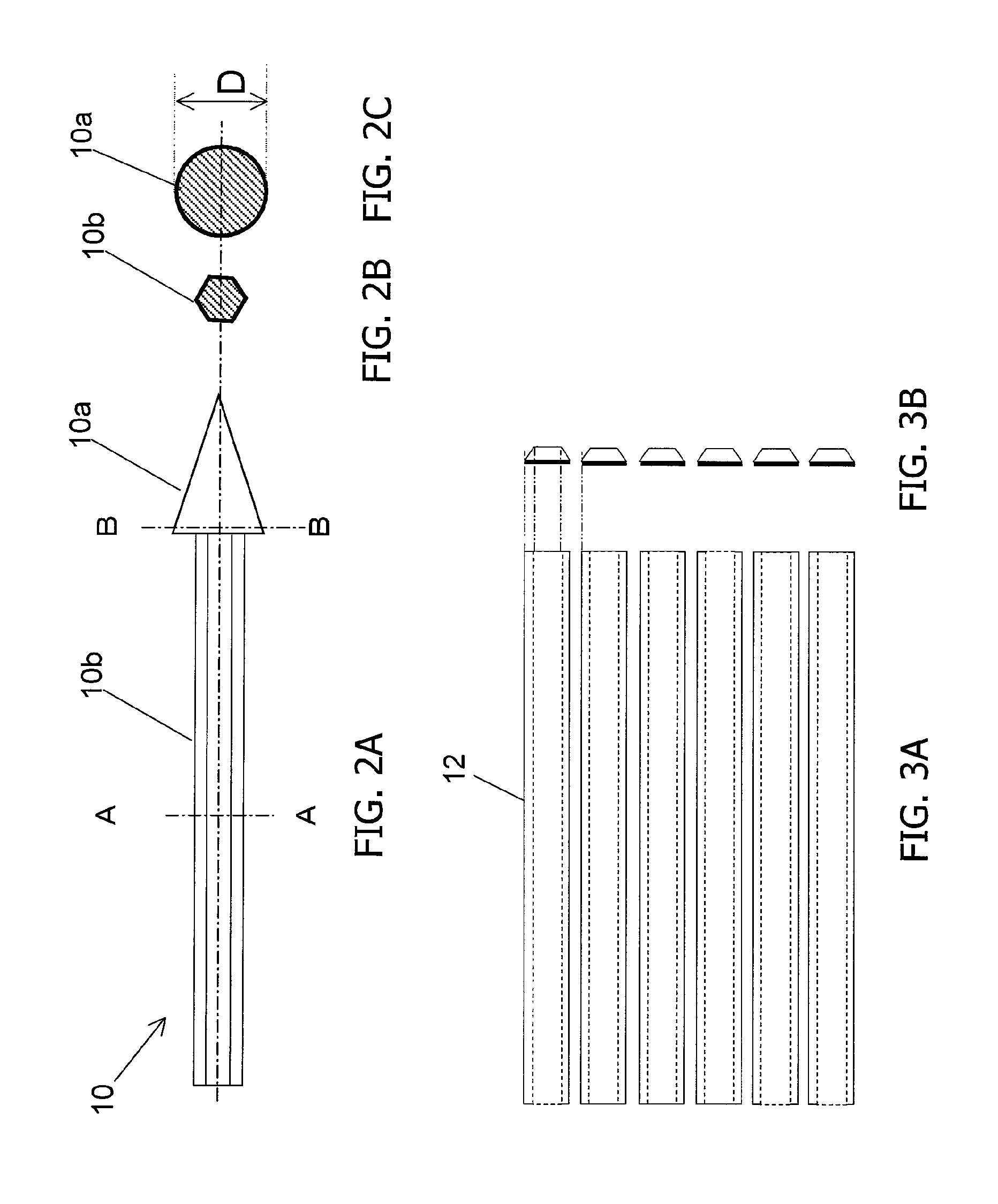
[0042]FIG. 1A to FIG. 1C show configuration examples of the brain probe of an embodiment of the present invention. FIG. 1A is a schematic view of the brain probe. FIG. 1B is a cross-sectional view taken along the A-A line in FIG. 1A. FIG. 1C is a cross-sectional view taken along the B-B line in FIG. 1A.

[0043]The brain probe 1 is configured to have a core probe 10 and a plurality of electrode plates 12 that cover the side surface of the core probe 10 and are attached to the side surface of the core probe 10 so that the side surface thereof forms a hexagon. By using a hexagonal configuration of electrode plates it is possible to eliminate the spread of reception sensitivity caused by orientation, as compared with a biplane configuration, and realize an omnidirecitonal brain probe in ...


PUM

PropertyMeasurementUnit
lengthaaaaaaaaaa
diameteraaaaaaaaaa
diameteraaaaaaaaaa

Abstract

A brain probe includes: a core probe made from a metal; and n electrode plates attached so as to cover an entire side surface circumference of the core probe and forming n side planes providing an n-angular cross section (n is an integer equal to or greater than 3). Each of the electrode plates is manufactured by a LSI manufacturing process, and provided with at least one electrode and a lead-out wiring extending in a longitudinal direction of a side plane from each of the at least one electrode.

Description

CROSS-REFERENCE TO RELATED APPLICATIONS[0001]This application is a continuation of international application PCT / JP2011 / 54246, filed on Feb. 25, 2011.TECHNICAL FIELD[0002]The present invention relates to a brain probe that detects electric signals from the brain cells and outputs electric signals stimulating the brain cells, and the present invention also relates to a method for manufacturing the same.BACKGROUND ART[0003]The aging of society in recent years is accompanied by the increase in the number of patients with developed diseases (for example, Parkinson disease, and paralysis, epilepsy) caused by brain disorder. Clarification of brain functions, in particular clarification of nerve circuit activity inside the brain is an indispensible means for developing methods for treating the diseases caused by brain disorder. Brain probes that are inserted into the brain to detect electric signals (brain waves) of brain cells have been used for such purpose. Furthermore, the brain probes...

Claims


Application Information

Patent Timeline
Patent Type & Authority Patents(United States)
IPC IPC(8): A61B5/0478A61B1/05H01R43/00A61B5/296
CPCA61B5/04001H01R11/18A61N1/0534A61B2562/046A61B2562/125Y10T29/49117H01R2201/12A61B5/24A61B5/291A61B5/293
Inventor MOTOYOSHI, MAKOTOKOYANAGI, MITSUMASAMUSHIAKE, HAJIMETANAKA, TETSUKATAYAMA, NORIHIRO
Owner TOHOKU MICROTEC
Why Eureka
Try Eureka