Liquid processing apparatus, liquid processing method, and storage medium

Inactive Publication Date: 2009-03-05
TOKYO ELECTRON LTD
View PDF5 Cites 17 Cited by
  • Summary
  • Abstract
  • Description
  • Claims
  • Application Information

AI Technical Summary

Benefits of technology

[0032]Due to this structure, even when there is employed a method in which the substrate to be processed is processed by the hydrofluoric process liquid and is then dried by the organic solvent, the alkaline component in the casing can be removed by the removing mechanism, or the invasion of an alkaline component into the casing can be prevented by the invasion preventing mechanism, before the substrate to be processed is dried. Therefore, the generation of marks on the substrate to be processed can be

Problems solved by technology

Namely, after the wafer is processed by a process liquid containing an ammonia component (alkaline component) and by hydrof

Method used


Image

  • Liquid processing apparatus, liquid processing method, and storage medium
  • Liquid processing apparatus, liquid processing method, and storage medium
  • Liquid processing apparatus, liquid processing method, and storage medium

Examples


first embodiment

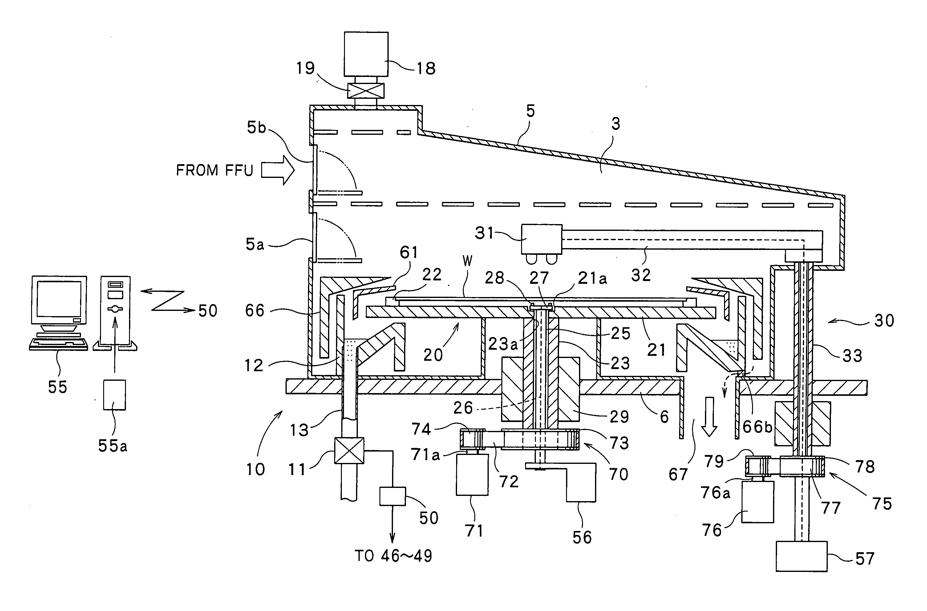
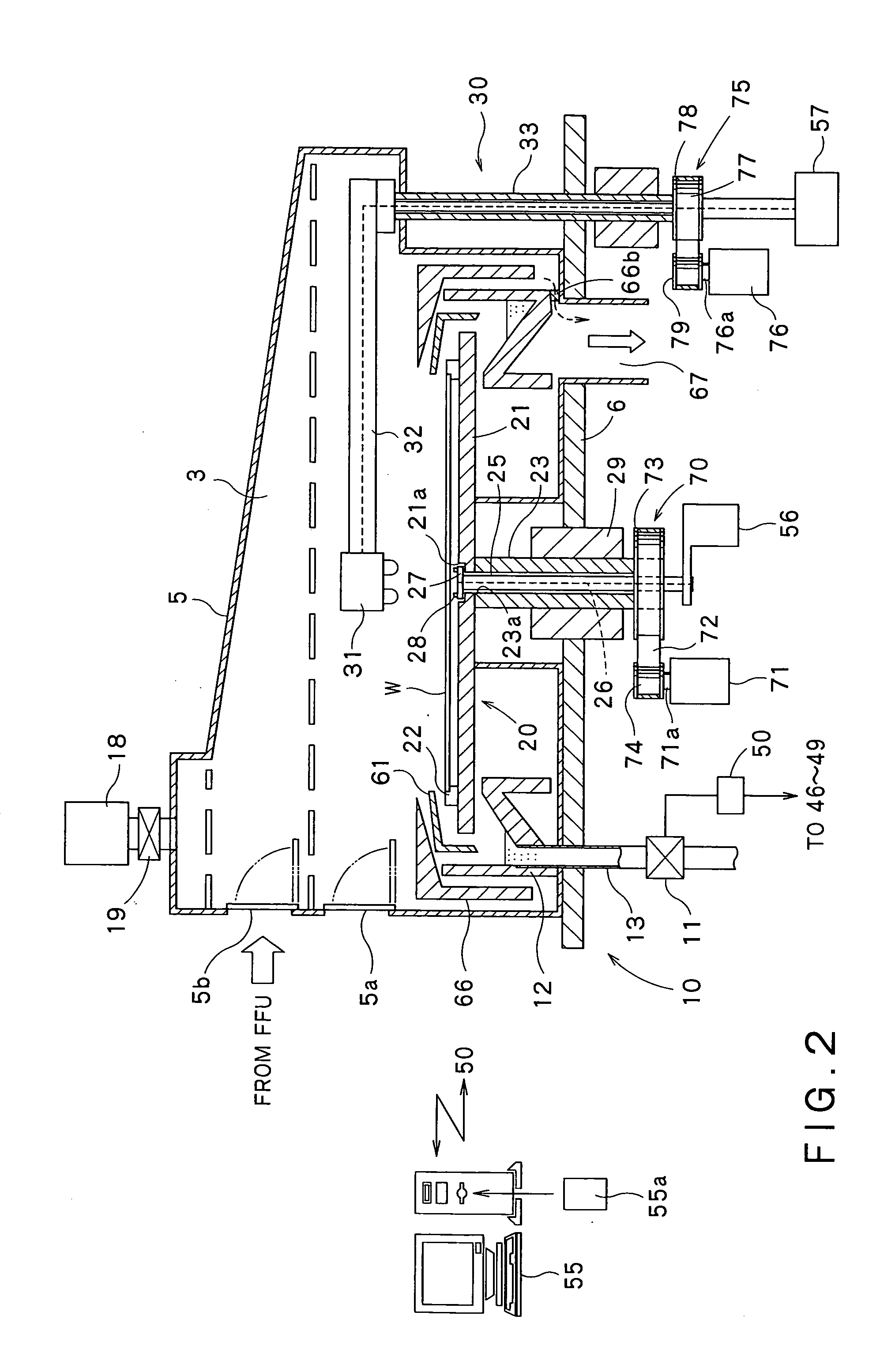
[0041]A first embodiment of a liquid processing apparatus, a liquid processing method, and a storage medium, of the present invention is described herebelow with reference to the drawings. FIGS. 1 to 5 show the first embodiment of the present invention.

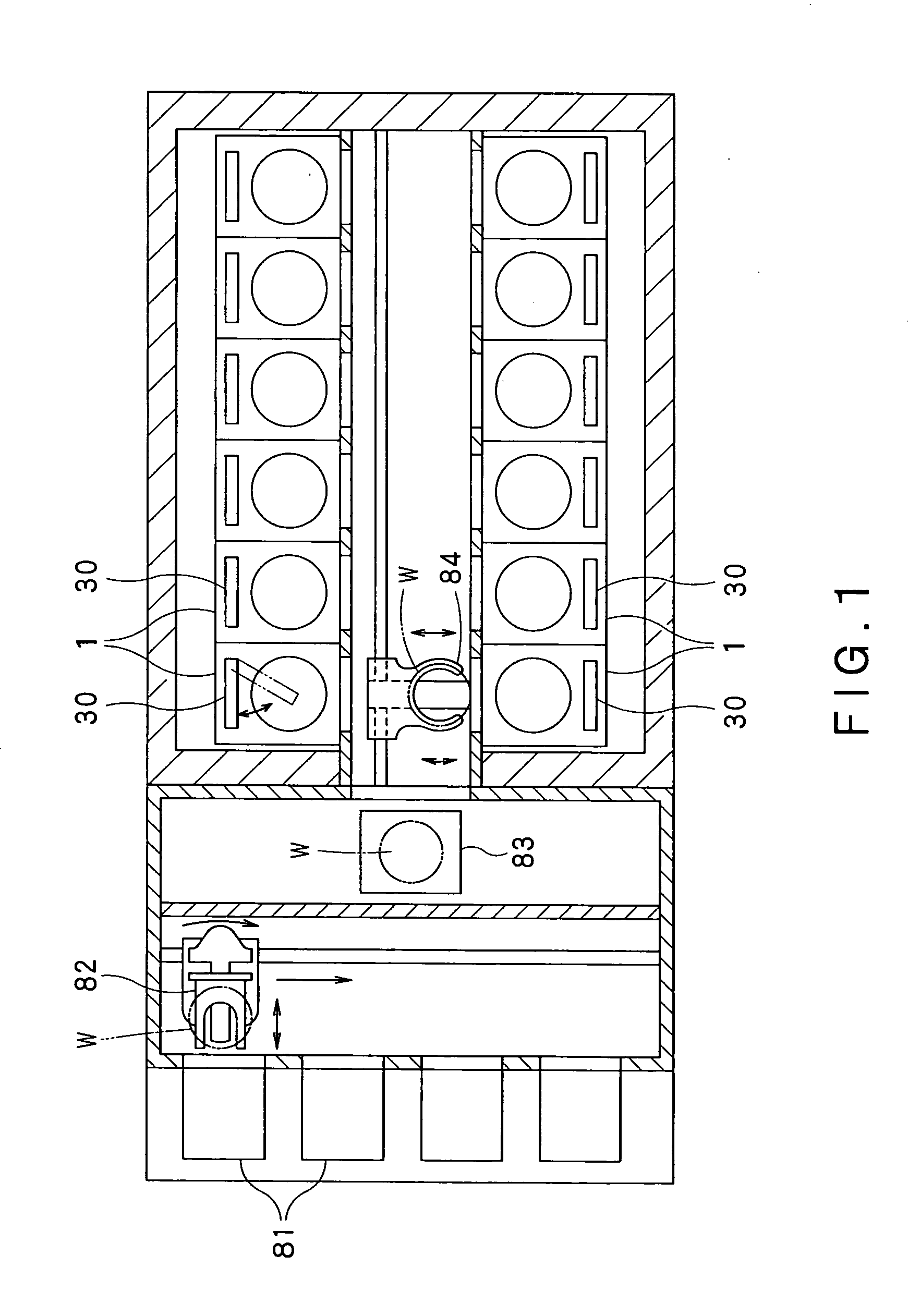
[0042]As shown in FIG. 1, a liquid processing system includes: a stage 81 in which a carrier loaded from outside is placed, the carrier accommodating a semiconductor wafer W (hereinafter simply referred to also as “wafer W”) that is a substrate to be processed; a transfer arm 82 that takes out the wafer W accommodated in the carrier; a shelf unit 83 on which the wafer W taken out by the transfer arm 82 is placed; and a main arm 84 that receives the wafer W placed on the shelf unit 83 and conveys the wafer W into a liquid processing apparatus 11. Incorporated in the liquid processing system are the plurality of liquid processing apparatuses (twelve in this embodiment). FIG. 1 is an upper plan view of the liquid processing system includ...

second embodiment

[0093]Next, a second embodiment of the present invention is described with reference to FIG. 6. In the second embodiment shown in FIG. 6, a cleaning mechanism (removing mechanism) 10 that removes an alkaline component adhering to a draining cup 12 is constituted, in place of the cleaning-liquid supplying mechanism, the draining pipe 13, and the blocking valve 11, by a cleaning-liquid jetting mechanism 15 that jets deionized water (cleaning liquid) D to the draining cup 12 so as to remove the alkaline component adhering to the draining cup 12. Further, an annular exhaust cup 66 located on an outer peripheral side of the draining cup 12 is capable of being moved in an up and down direction (see, arrow A2 in FIG. 6). Other structures of the second embodiment are substantially the same as those of the first embodiment shown in FIGS. 1 to 5.

[0094]In the second embodiment shown in FIG. 6, the same parts as those of the first embodiment shown in FIGS. 1 to 5 have the same reference numbers...

third embodiment

[0105]Next, a third embodiment of the present invention is described with reference to FIG. 7. In the third embodiment shown in FIG. 7, in place of the provision of the cleaning mechanism 10 that removes the alkaline component in the casing 5, a dry-gas supplying part 18 serves as a pressurizing mechanism (invasion preventing mechanism) that prevents invasion of an alkaline component into a casing 5. Specifically, an air pressure of a dry gas flowing into the casing 5 from the dry-gas supplying part 18 is increased to thereby prevent the invasion of an alkaline component into the casing 5. Other structures of the third embodiment are substantially the same as those of the first embodiment shown in FIGS. 1 to 5.

[0106]In the third embodiment shown in FIG. 7, the same parts as those of the first embodiment shown in FIGS. 1 to 5 have the same reference numbers, and a detailed description thereof is omitted.

[0107]As shown in FIG. 7, connected to the casing 5 is a pressurizing mechanism 1...


PUM


Abstract

A liquid processing apparatus 1 comprises a casing 5, a substrate holding mechanism 20 that holds a wafer (substrate to be processed) W, a process-liquid supplying mechanism 30 that supplies a process liquid, a draining cup 12 that receives a process liquid, and a draining pipe 13 that discharges a process liquid outside. The process-liquid supplying mechanism 30 includes a first chemical-liquid supply mechanism that supplies a hydrofluoric process liquid, and a drying-liquid supplying mechanism that supplies an organic solvent for drying a wafer W. A control part 50 causes the first chemical-liquid supplying mechanism to supply a hydrofluoric process liquid, and then causes the drying-liquid supplying mechanism to supply an organic solvent. In addition, before the control part 50 causes the drying-liquid supplying mechanism to supply an organic solvent, the control part causes a cleaning mechanism 10 to remove an alkaline component in a casing 5.

Description

CROSS REFERENCE TO RELATED APPLICATIONS[0001]This application is based upon and claims the benefit of priority from the prior Japanese Patent Application No. 2007-225868 filed on Aug. 31, 2007, the entire contents of which are incorporated herein by reference.FIELD OF THE INVENTION[0002]The present invention relates to: a liquid processing apparatus; a liquid processing method; and a storage medium storing a computer program executable by a computer for performing the liquid processing method; the apparatus and the method employing a method including a drying step by means of an organic solvent, the drying step after a processing step by means of a hydrofluoric process liquid.BACKGROUND ART[0003]As a method of removing particles adhering to a wafer to be processed, there has been conventionally known a liquid processing method in which, a solution containing mixture of ammonia and hydrogen peroxide is discharged onto the wafer while the wafer is being rotated, and then hydrofluoric ...

Claims


Application Information

Patent Timeline
IPC IPC(8): B08B3/08B08B3/02
CPCH01L21/67028H01L21/67051H01L21/67034B08B3/02B08B3/08H01L21/304
Inventor MINAMI, TERUOMIITO, NORIHIROKAMIKAWA, YUJI
Owner TOKYO ELECTRON LTD
Why Eureka
Try Eureka