Projectile sealing arrangement
a technology of sealing arrangement and projectile, which is applied in the direction of weapons, ammunition loading, rockets for air display, etc., can solve the problems of reducing the relative complexity and cost of manufacturing barrel assemblies utilizing operative sealing engagement with the barrel, and achieves the effect of reducing the relative complexity and cost of manufacturing barrel assemblies
- Summary
- Abstract
- Description
- Claims
- Application Information
AI Technical Summary
Benefits of technology
Problems solved by technology
Method used
Image
Examples
first embodiment
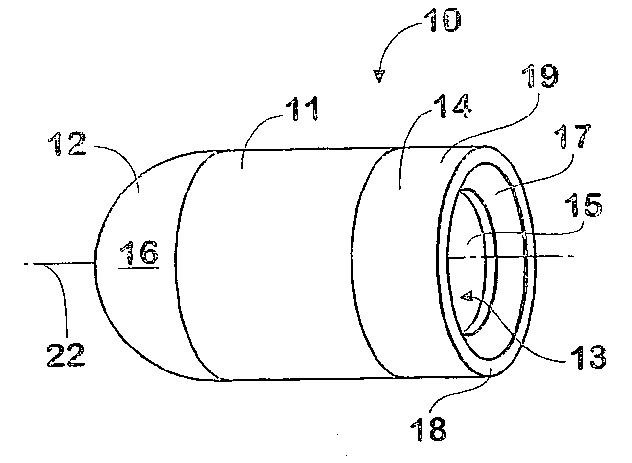
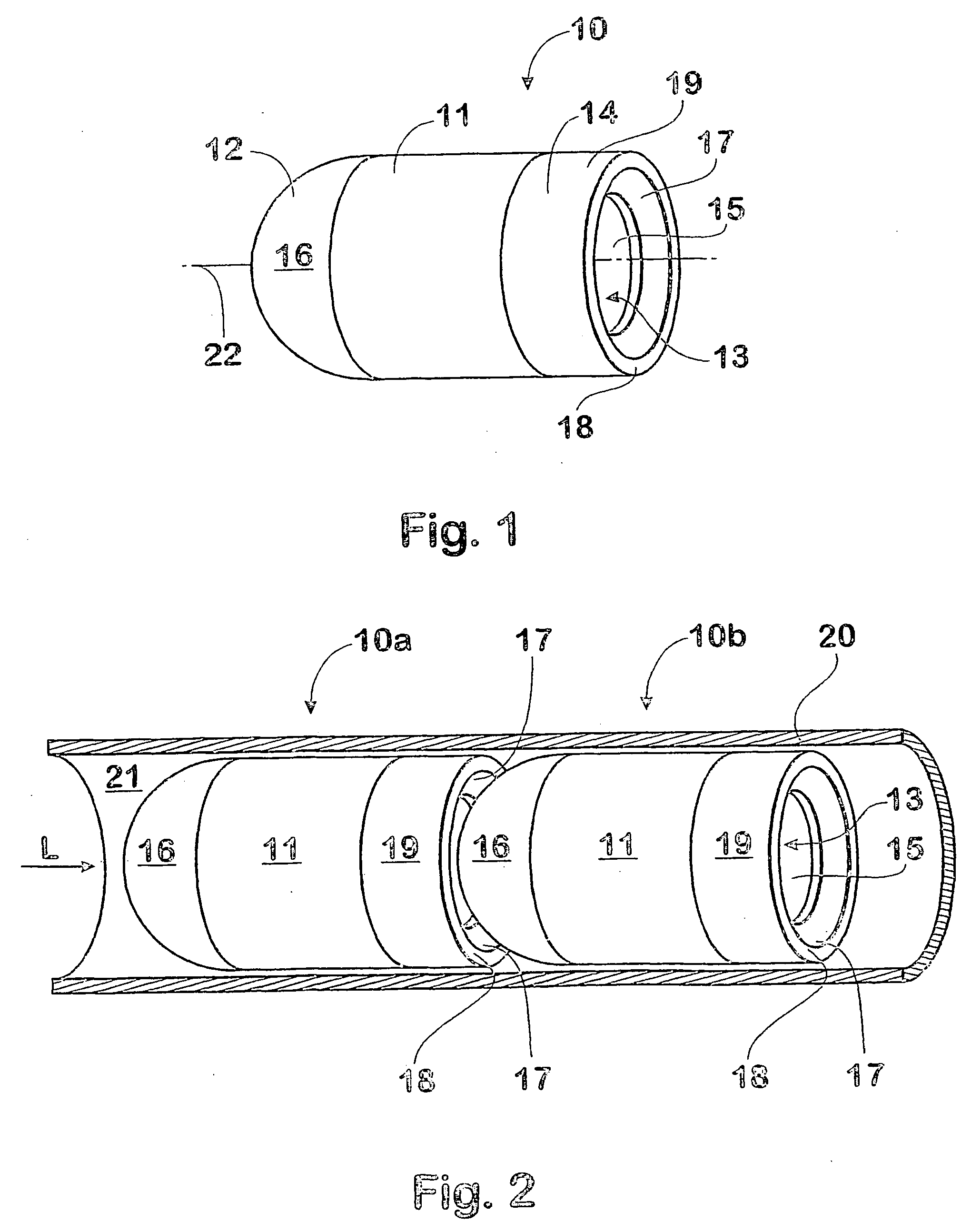
[0044] The projectile assemblies 10 of the first embodiment illustrated in FIGS. 1 and 2 each include a body 11 having a head or forward portion 12 and a mouth or rearward opening 13 at a tail portion 19, which opening communicates with a cavity 14 provided in the projectile body. The cavity 14 contains a discrete propellant charge 15 together with ignition means (not shown) for igniting the propellant charge. It will be appreciated that upon ignition of the propellant, suitably by electronic control means, combustion products including propellant gas will exit the projectile cavity 14 via the mouth 13 at the tail 19 of the projectile with considerable force.
[0045] In the first embodiment, a forward sealing surface 16 of the projectile head 12 is convex, having a simple hemispherical shape, whilst the mouth 13 has a peripheral sealing surface 17 that is provided or formed, at least in part, with a complementary concave shape to the hemispherical sealing surface 16 of head 12. The pr...
second embodiment
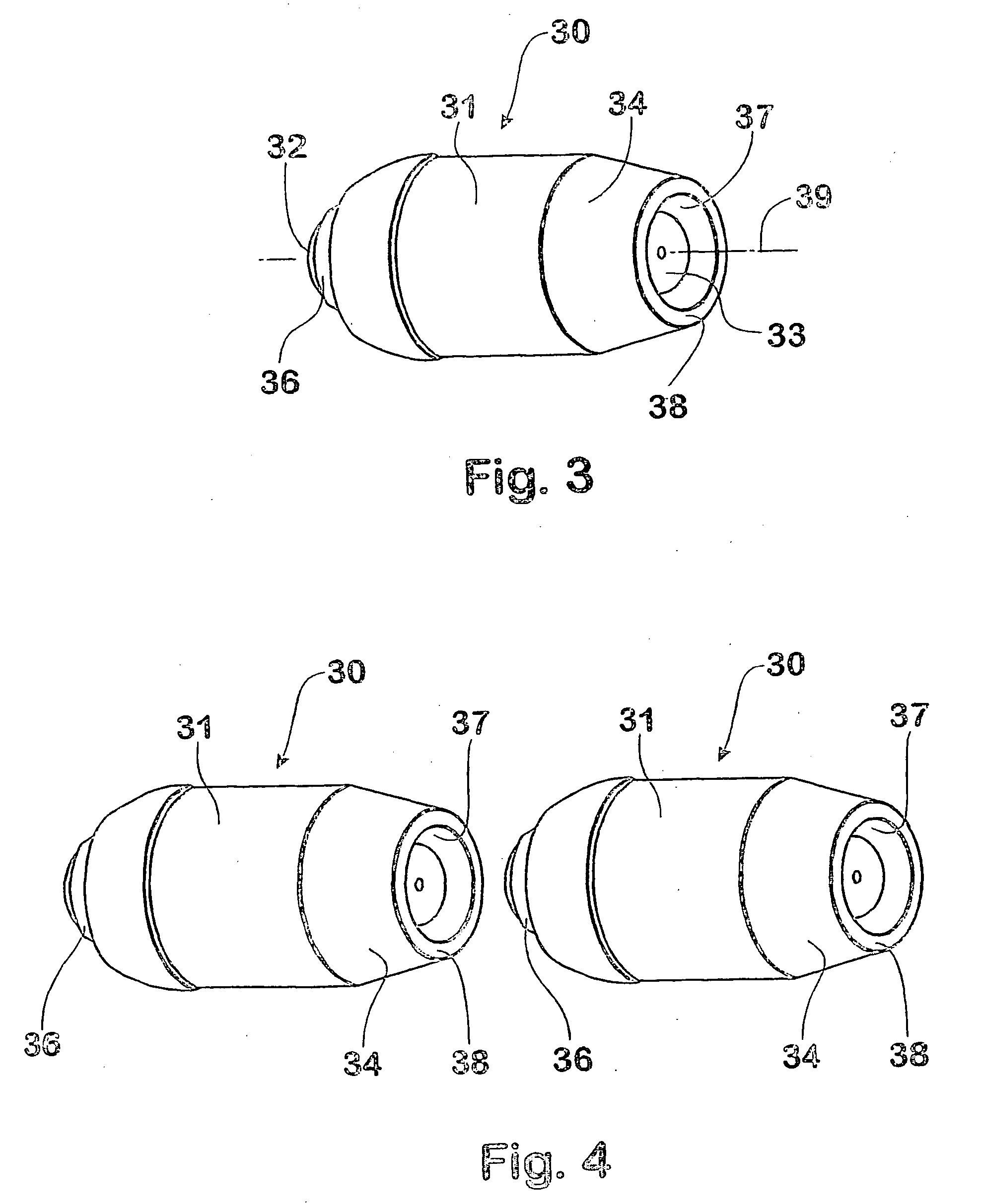
[0050] A projectile 30 in accordance with the invention is illustrated in FIG. 3. The projectile 30 includes a body 31 having a reduced diameter head or forward portion 32 and a mouth or rearward opening 33 at a tail portion which mouth communicates with a cavity (not shown) provided in the projectile body. The projectile body 31 includes a frustro-concial tail portion 34 which terminates at an annular rear face 38 having a reduced diameter relative to the projectile body generally. The internal cavity contains a discrete propellant charge 35 together with ignition means (not shown) for igniting the propellant charge. The arrangements for igniting the propellant charge may suitably be similar to those described in the earlier International Patent Application PCT / AU94 / 00124, assigned to the present applicant.
[0051] A forward sealing surface 36 is provided on the projectile head, together with a complementary rearward sealing surface 37 at the periphery of the rearward opening 33, whi...
third embodiment
[0054] In other variations of the third embodiment, the sealing means may comprise an adhesive sealing material that forms a seal between abutting projectile assemblies in situ, and might also function to retain a plurality of projectiles in a chain for ease of loading into a barrel. A propellant charge 45 is retained with the body of the projectile assembly 40, and may be formed as a solid block or as flowable material, such as powder or granules, as in the present embodiment.
[0055] This embodiment further includes a closure for the rearward opening 43, in the form of a burstable disc 46, for retaining the flowable propellant charge 45. The closure, which may alternatively be formed of a combustible material rather than a burstable disc, includes retaining means that releasably engage with complementary retaining means on an adjacent projectile head. The retaining means in the present embodiment are formed by a spigot member 47 on the head, and by a socket member 48 provided in the...
PUM
 Abstract
Description
Claims
Application Information
 - R&D
- Intellectual Property
- Life Sciences
- Materials
- Tech Scout
- Unparalleled Data Quality
- Higher Quality Content
- 60% Fewer Hallucinations
Browse by: Latest US Patents, China's latest patents, Technical Efficacy Thesaurus, Application Domain, Technology Topic, Popular Technical Reports.
© 2025 PatSnap. All rights reserved.Legal|Privacy policy|Modern Slavery Act Transparency Statement|Sitemap|About US| Contact US: help@patsnap.com


