Nozzle for use in rotational casting apparatus

a technology of rotating casting and nozzle, which is applied in the direction of dough shaping, application, manufacturing tools, etc., can solve the problems of increasing the difficulty of adjusting the nozzle, requiring more frequent downtime, and clogging the dispensing head, and achieves the effect of significant increasing the flow

Active Publication Date: 2005-12-08
KASTALON
View PDF33 Cites 6 Cited by
  • Summary
  • Abstract
  • Description
  • Claims
  • Application Information

AI Technical Summary

Benefits of technology

[0012] It is also the primary objective of the present invention to provide such a plurality of interior discharge-passageways such that the exit of the nozzle of the invention defines a plurality of spaced-apart discharge or exit outlets or openings, with each discharge or exit openings having the same, slit-like shape, whereby a wider spreading of material during discharge is provided without significantly increasing flow.

Problems solved by technology

A considerable problem with rotational casting machines is the trade-off of forming a liquid polyurethane having a desired viscosity and reactivity in order to prevent run-off or dripping of the applied elastomer from the body being coated during the coating process, and the need to prevent the clogging of the dispensing head attached to, and forming part of, the mixing head during the coating-application process.
If the viscosity is made too great or reactivity too fast, then the dispensing head tends to become clogged faster, requiring more frequent down-time in order to unclog and clean the dispensing head.
However, the problem with these prior-art dispensers is that each hypothetical section of the liquid elastomer exiting the dispensing head at the exit thereof has not, typically, had the same dwell-time in the dispensing nozzle along the width and the length thereof, whereby there is not ensued that the exothermically formed elastomer has the same properties throughout when applied to the body to be coated.
However, even changing sheet-dies in order to accommodate materials of different viscosity / reactivity in order to prevent frequent clogging of the sheet-die in order to obtain the desired coating thickness, has still not solved the problem of the frequent clogging and associated frequent down-times when sheet-die nozzles are used.
Over time, a build-up of solidified material develops, causing clogging at or near the exit, as well as interiorly thereof which forms the build up of solidified whiskers or “stalactites” of reacted material that interferes with the material deposition on the body.
If the exiting stream of liquid material were too thick, or tall, the interior portion of the reacting liquid while still in a fluid state would not have built enough viscosity to support the column height of the stream and would run or drip off the body to which it was applied.
If the reactivity were adjusted to build sufficient viscosity quickly enough to support the stream column height, the stream would not be liquid enough to flow onto the precedingly-applied material and an uneven coating would result.
This has, in fact, been one of the serious problems of the prior-art nozzle for rotational casting machines; that is, in a relatively short period of time, the nozzle becomes clogged and unusable, requiring the disassembly and cleaning thereof, which also causes considerable down-time to the rotational casting machine.
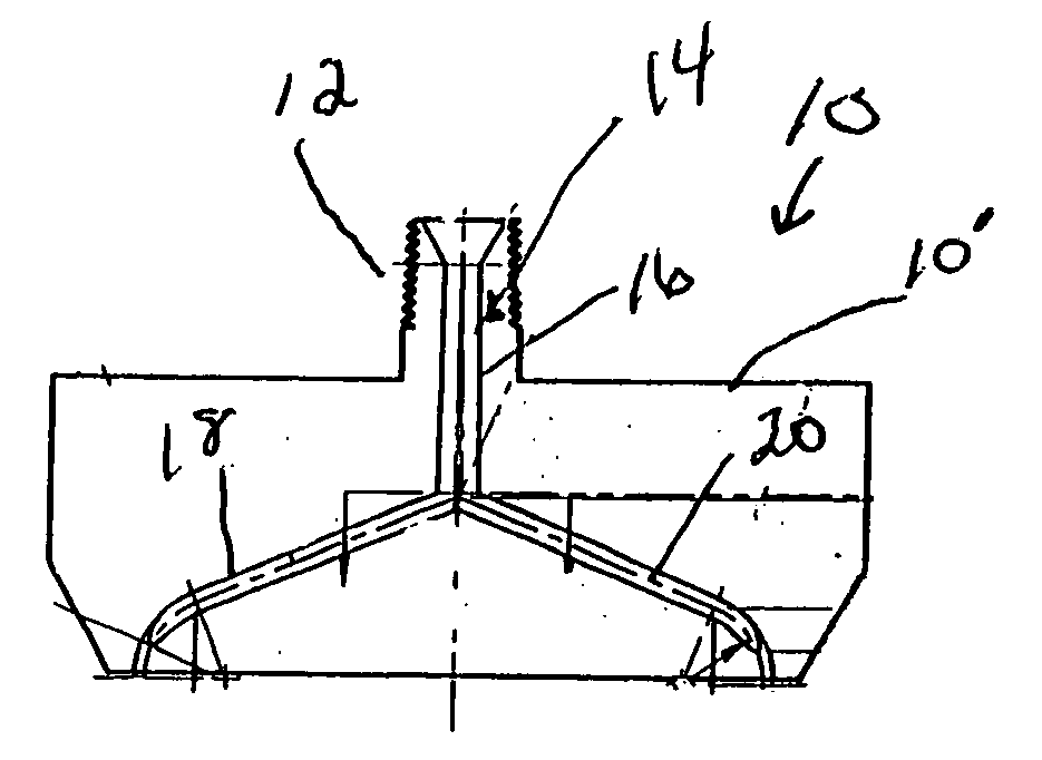
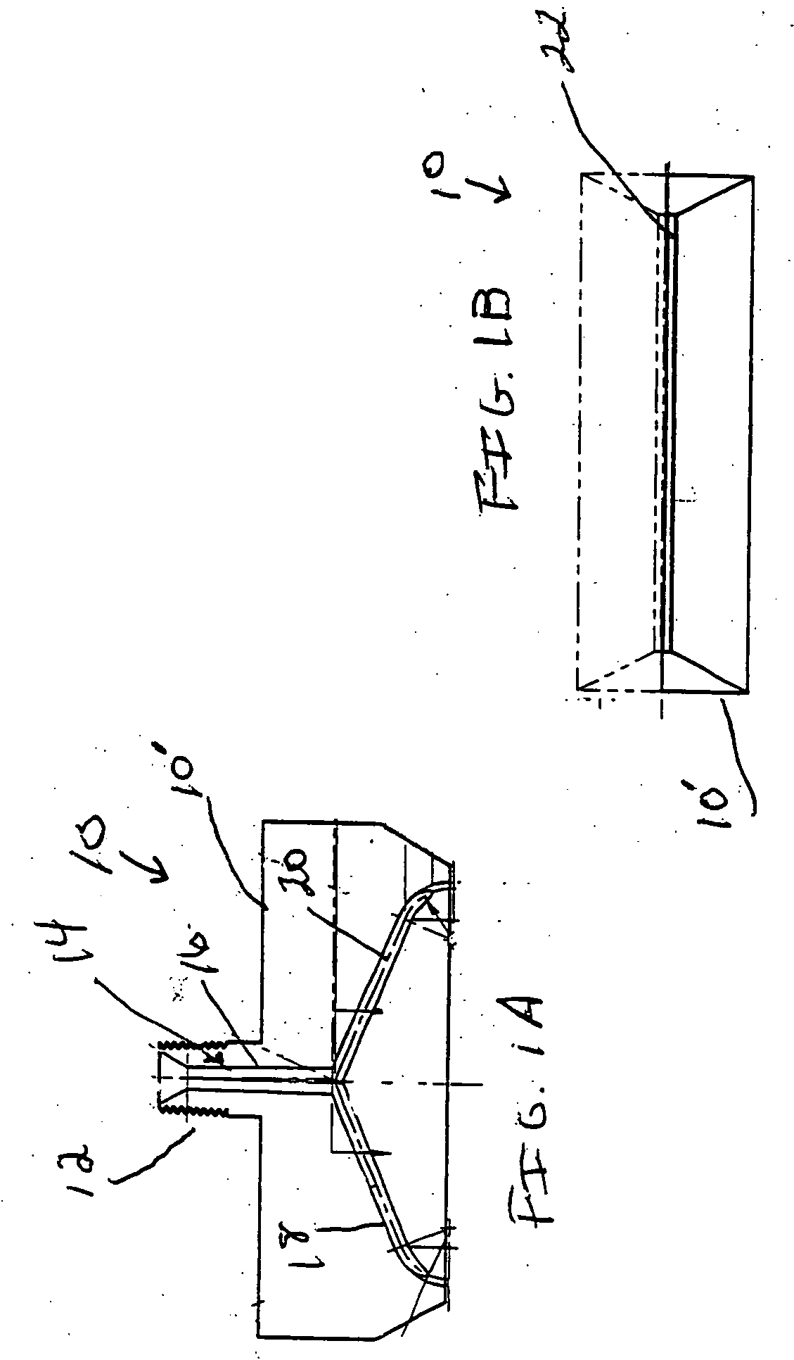
Moreover, since the slit-opening 22 is fed by two branches feeding into the ends of the slit-opening, the liquid-material application onto to the body to be coated is ofitimes inconsistent and uneven, and is also limiting in the range that the distance the nozzle may be relative to the body to be coated.
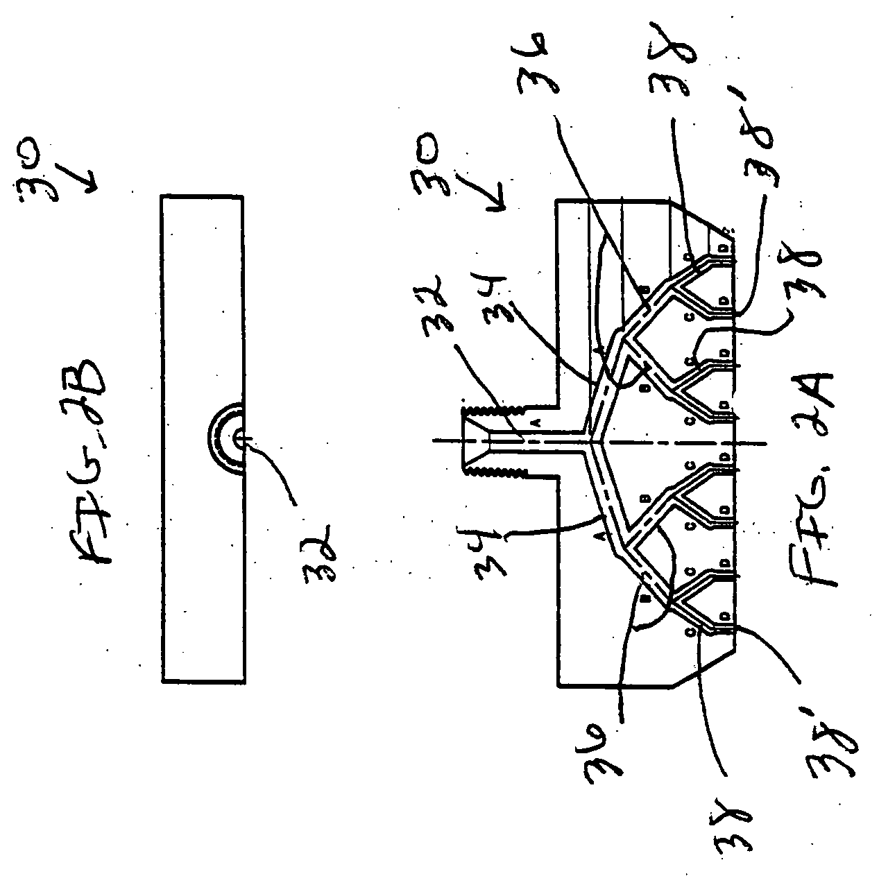
However, the prior-art nozzle 30 has not addressed nor overcome the problem of consistent and frequent clogging of interior passageways described above with regard to the nozzle 10 of FIGS. 1A and 1B.
If the rotational speed of the rotating body were to be too great in comparison to the exit speed of the liquid material from the nozzle-exit, then the applied coat may be thinner than required, and require additional coating layers to be applied to the rotating body, reducing the efficiency of the process, and also would cause air to become entrapped in the applied liquid, causing air blisters to form, since there would not be enough time for the applied stream to push out the air between the applied stream and the surface of the rotating body.
On the other hand, if the rotational speed were to slow, then productivity and efficiency of the process would be adversely affected, would also increase the likelihood of premature curing, causing the eventual clogging of the nozzle, and uneven application of the coating to the rotating body.
Similarly, if the relative translational motion between the exit-nozzle and the rotating body were too slow, the efficiency and productivity of the process would be adversely affected, and would also cause an applied coating that would be too thick, thus causing dripping of the applied liquid from the body being coated, as well as potentially uneven thickness of the applied coat.
The need and requirement for optimal correspondence between exit speed of the liquid from the nozzle, the thickness of the exiting stream of liquid, the rotational speed of the rotating body being coated relative to this exit speed of the liquid from the nozzle, and the relative translational speed between the nozzle and the rotating body being coated has imposed significant constraints as to linear distance the exit of the nozzle of the rotating casting machine may be from the surface of the rotating body being coated.
A distance greater than 5 mm. has been found to cause excessive clogging of the nozzle, with a concomitant increase of downtime of the machine for unclogging the nozzle.
The increase in speed of the liquid through the nozzle increases turbulent flow in the nozzle, thus increasing the dwell-time of the liquid in the nozzle, and the increased curing thereof in the nozzle, with the ensuing clogging of the nozzle, as discussed hereinabove.
Besides the increased clogging of the nozzle, air blisters form in the applied coating of liquid, for the reasons described hereinabove due to the increased exit speed of the liquid from the nozzle-exit.
Another considerable problem with the sheet-die nozzle of FIG. 1 is that the size of the rotating body that may be coated with the liquid exiting therefrom is limited.
Cylindrical bodies having a diameter less than approximately five inches have not been able to effectively coated with liquid.

Method used


Image

  • Nozzle for use in rotational casting apparatus
  • Nozzle for use in rotational casting apparatus
  • Nozzle for use in rotational casting apparatus

Examples


Embodiment Construction

[0025] Referring now to the drawings in greater detail, and to FIGS. 3A-3C for now, there is shown a half-section 40 of the nozzle of the present invention, it being understood that the other half-section of the nozzle of the invention is substantially identical. Each half-section 40 has a plurality of holes through which pass bolts for securing the two-halves together, with alignment pins cooperating with openings in the other-half section for initially aligning the half-sections together, in the manner described in above-mentioned copending application Ser. Nos. 10 / 646,343 and 10 / 659,732. Each half-section 40 has an upper threaded portion 46, whereby after the two half-sections have been attached, there is provided an attachment section for securing the nozzle 40 to the mixing head of a rotational casting machine in the conventional manner, in which mixing head are mixed the prepolymers for forming the polyurethane used to coat a rotating body held by the rotational casting machin...


PUM

PropertyMeasurementUnit
diameteraaaaaaaaaa
distanceaaaaaaaaaa
diameteraaaaaaaaaa

Abstract

For use in a rotational casting machine used for coating a rotating body with elastomer, such as polyurethane, there is provided a nozzle used for dispensing the liquid polyurethane onto the rotating body to be coated. The nozzle of the invention has a plurality of liquid-flow interior discharge-passageways each of which has an inlet connected to a sub-branch tube, which sub-branch tube is, in turn, is fluidly connected to a main branch that, in turn, is connected to a main inlet-passageway having the inlet that is directly connected to mixing head. Each discharge-passageway, or exit-passageway, changes in cross-sectional shape along the longitudinal axis thereof from its inlet to its outlet such that the cross-sectional area from the inlet to the outlet thereof gradually and minimally increases, whereby at least substantial laminar flow of the liquid is achieved with the concomitant reduced dwell-time of the liquid therein, in order to reduce in-nozzle reaction and subsequent clogging of the nozzle. The exit of the nozzle itself is constituted by the plurality of spaced-apart exit-openings or outlets of the discharge-passageways, where each such exit-opening or outlet is formed as a narrow, elongated slit or opening.

Description

CROSS REFERENCE TO RELATED APPLICATIONS [0001] Reference is had to copending, commonly-owned applications Ser. No. 10 / 646,343 filed on Aug. 22, 2003 and Ser. No. 10 / 659,732 filed on Sep. 10, 2003, which applications are incorporated by reference herein.BACKGROUND OF THE INVENTION [0002] The present invention is directed to a nozzle for use in a rotational casting machine used for applying one or more coats of liquid elastomer, such as polyurethane, to a rotating body, such as a pipe, cylinder, and the like, whereby an elastomer covering or coating is applied to the exterior or interior of the pipe, cylinder, or the like. The body being coated may be used in steel or paper mills, or many other industries, in order to protect the body proper during end-use, as well as for providing other desired properties. Rotational casting machines, that rotationally mount a body to be coated with polyurethane or other liquid elastomer, are disclosed, for example, in U.S. Pat. Nos. 5,601,881 and 5,...

Claims


Application Information

Patent Timeline
Patent Type & Authority Applications(United States)
IPC IPC(8): B05C11/02B29C41/04B29C41/08B29C41/10B29C48/30
CPCB29C41/04B29C41/10B29C41/085
Inventor DEMENT, R. BRUCEWERSTLER, PAULSNYDER, ROBERT G. III
Owner KASTALON
Why Eureka
Try Eureka