Brake

a technology of brakes and moving parts, applied in the field of brakes, can solve the problems of cost and space efficiency, disadvantages of providing the brake for the moving member, etc., and achieve the effect of simple structur

Inactive Publication Date: 2005-12-08
FANUC LTD
View PDF2 Cites 9 Cited by
  • Summary
  • Abstract
  • Description
  • Claims
  • Application Information

AI Technical Summary

Benefits of technology

[0006] In a brake according to the present invention in a rotating shaft or a direct-acting slide supported by a fluid bearing, fluid supplied to one of opposed bearing faces of the fluid bearing is interrupted, the rotating shaft or the direct-acting slide is pressed against the bearing face where the fluid is interrupted by pressure of the fluid on the bearing face where the fluid is not interrupted, and a brake face provided to the rotating shaft or the direct-acting slide is brought into contact with a static portion to thereby brake the rotating shaft or the direct-acting slide.
[0007] With the brake of the invention, the rotating shaft or the direct-slide can be braked by only selectively interrupting any of the plurality of paths of the pressurized fluid toward the bearing faces of the fluid bearing. Therefore, it is possible to provide a low-cost brake with a simple structure.

Problems solved by technology

It is disadvantageous to provide the brake for the moving member such as the rotating shaft and the direct-acting slide in respects of cost and space efficiency.

Method used


Image

  • Brake
  • Brake
  • Brake

Examples


first embodiment

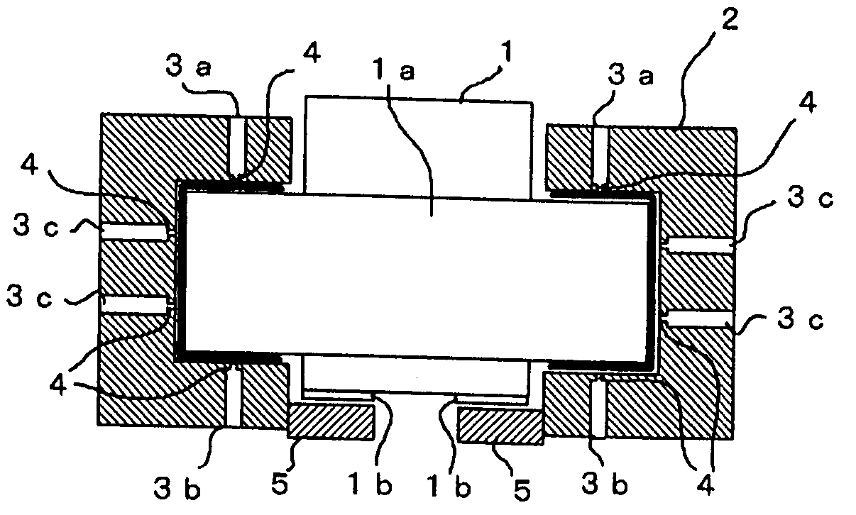
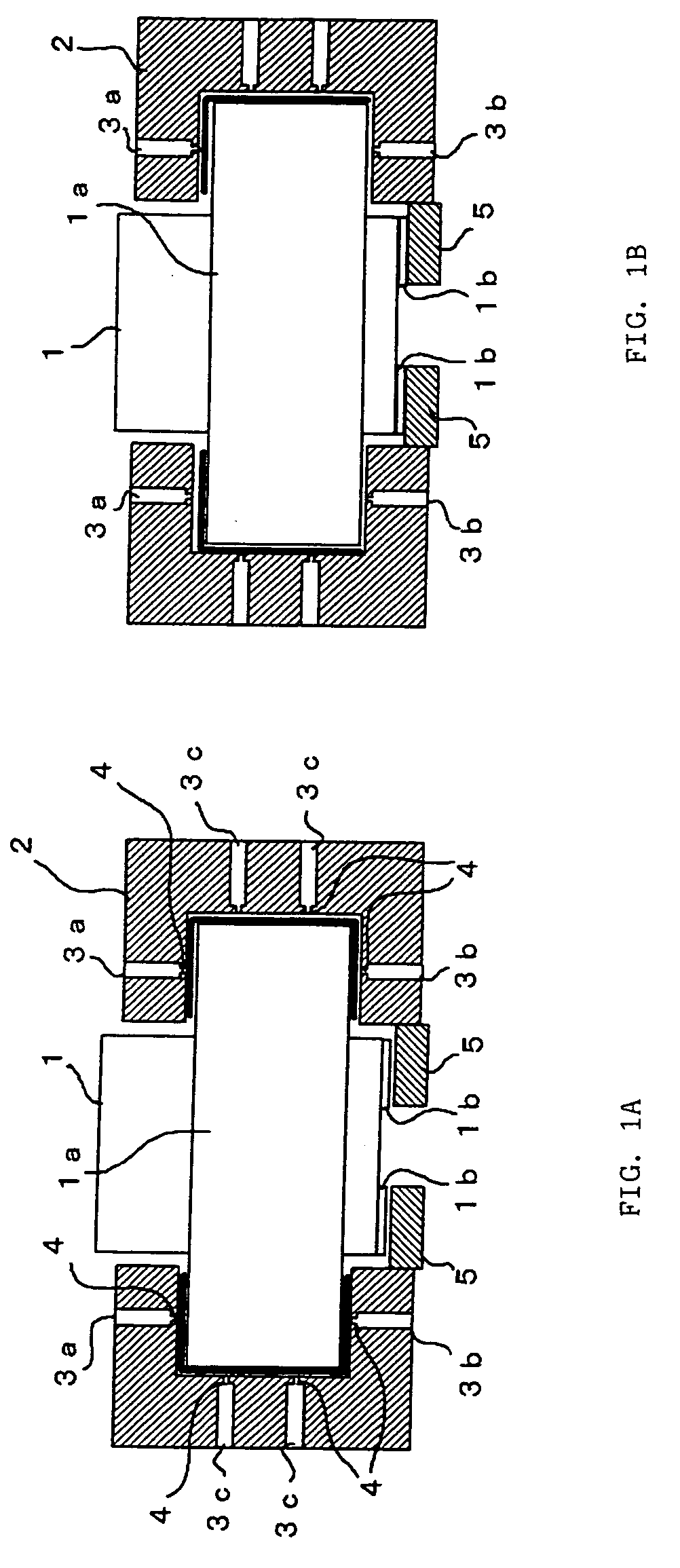
[0013]FIGS. 1A and 1B are schematic diagrams of the brake according to the present invention. In this embodiment, the brake is applied to a rotating shaft supported on a fluid bearing and is different from a prior-art fluid bearing for a rotating shaft in that a static portion 5 and a brake member 1b forming the brake are provided at a lower portion of the fluid bearing. FIG. 1A shows a state in which a brake is not applied by the brake and FIG. 1B shows a state in which a brake is applied.

[0014] A flange-shaped disk 1a is integrally formed with a rotating shaft 1. A bearing member 2 is mounted in such a manner as to surround an outer peripheral face and upper and lower end faces of the disk 1a. In the bearing member 2, first to third passages 3a to 3c through which fluid such as pressurized air passes are formed.

[0015] From each the first passage 3a, the fluid is injected toward the upper end face of the disk 1a from a nozzle portion 4 formed at a tip end portion of the passage 3a...

second embodiment

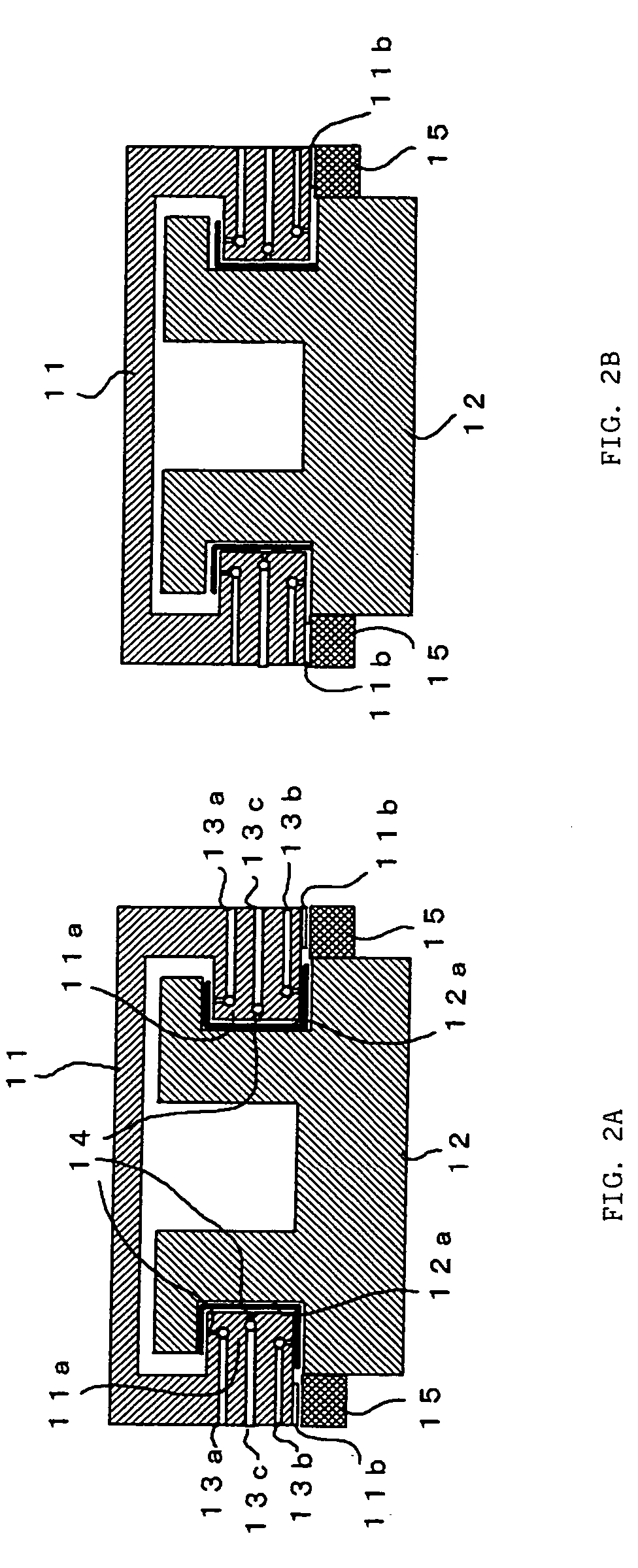
[0023]FIGS. 2A and 2B are schematic diagrams of the brake according to the invention. In this embodiment, the brake is applied to a direct-acting slide mechanism supported on a fluid bearing. FIG. 2A shows a state in which a brake is not applied by the brake and FIG. 2B shows a state in which a brake is applied.

[0024] On opposite sides of a base 12 of the direct-acting slide mechanism, recessed portion grooves 12a extending in a direction of direct action of a direct-acting slide portion 11 (in a direction perpendicular to a paper face of FIG. 2) and having rectangular sectional shapes are provided. On the other hand, in the direct-acting slide portion 11, projecting portions 11a inserted into the respective recessed portion grooves 12a of the base 12 are provided. Upper and lower inner faces and vertical wall faces of the recessed portion grooves 12a of the base 12 respectively face upper and lower outer faces and tip end vertical faces of the projecting portions 11a of the direct-...

third embodiment

[0036] In the third embodiment, as shown in FIG. 3A, pressurized fluid is supplied to respective passages 3a to 3c and rotating shaft 1, a disk 1a, and a bearing member 2 are supported while kept from contact with each other to thereby form a fluid bearing. Fluid supply toward one end face side of the disk 1a is interrupted, the disk 1a and the rotating shaft 1 are pushed by pressure of fluid toward the other end face side as shown in FIG. 3B, and the end face of the disk 1a is pressed against a thrust bearing face to which the fluid is not supplied to thereby brake and stop the rotating shaft 1 which is rotating. In the case shown in FIG. 3, the fluid supply to the second passages 3b is interrupted and the disk 1a is pressed downward by pressure of the fluid supplied from the first passages 3a to thereby press the lower face of the disk 1a against the thrust bearing face on a lower side of the recessed portion groove 12a of the bearing member 2 to brake the rotating shaft 1.

[0037] ...


PUM


Abstract

Upper and lower thrust bearing faces and a peripheral radial bearing face are formed to surround peripheral and end portions of a disk provided to a rotating shaft supported by a fluid bearing. Pressurized fluid is supplied to the respective bearing faces from first to third fluid passages to thereby form fluid bearing faces. In order to rotate the rotating shaft, the pressurized fluid is supplied to all the passages to keep the rotating shaft and the disk from contact with a bearing member. In order to brake the rotating shaft, fluid supply to the second passage is interrupted. Thus, the rotating shaft is moved down by pressure on the bearing face on the first passage side and, as a result, the brake member comes in contact with the static portion to apply the brakes.

Description

BACKGROUND OF THE INVENTION [0001] 1. Field of the Invention [0002] The present invention relates to a brake of a moving member supported on a fluid bearing. [0003] 2. Description of the Prior Art [0004] In order to stop operation of a rotating body and a direct-acting body such as a rotating shaft, a rotating table, and a direct-acting slide, a brake is normally used. This brake stops moving operation of the rotating body or the direct-acting body by pressing a brake shoe, a brake band, or a brake pad against a member such as a brake drum and a brake disk rotating or moving together with the rotating body or the direct-acting body. In a case in which a fluid bearing for supporting a movable portion without contact by pressurized fluid is used as a bearing for the rotating body or the direct-acting body, the above-described brake is provided to brake the rotating body or the direct-acting body. [0005] It is disadvantageous to provide the brake for the moving member such as the rotat...

Claims


Application Information

Patent Timeline
Patent Type & Authority Applications(United States)
IPC IPC(8): F16C41/00B60T13/74F16C29/02F16C32/06F16D55/00F16D63/00F16D65/14
CPCF16C32/064F16C32/0696F16D2125/06F16D2121/02F16D65/186
Inventor KAWAI, TOMOHIKOMINAMI, HIROSHI
Owner FANUC LTD
Why Eureka
Try Eureka