Automated meter reading system, communication and control network for automated meter reading, meter data collector program product, and associated methods

Inactive Publication Date: 2005-12-08
ENERGY TECH GROUP
View PDF59 Cites 205 Cited by
  • Summary
  • Abstract
  • Description
  • Claims
  • Application Information

AI Technical Summary

Benefits of technology

[0030] Embodiments of the present invention also include a computer readable medium that is readable by a computer collecting utility usage data from a plurality of utility meters having utility meter sensors in communication with a plurality of communication nodes forming a mesh communication network. For example, a computer readable medium can include a set of instructions that, when executed by the computer, cause the computer to perform the operations of: polling the plurality of communication nodes in the mesh communication network to determine a strength of communication signal between a host computer and each of a plurality of communication nodes, each of the plurality of communication nodes also attempting to communicate with each other, responsive to the polling, to thereby determine a strength of the communication signals between each one of the plurality of communications nodes and another one of the plurality of communication nodes. The instructions also include those to perform the operations of determining an existence of substantial network interference, and varying or switching the radio frequency mode between a fixed radio frequency mode and a frequency hopping spread spectrum mode, as necessary, responsive to signal strength determination between nodes, to thereby enhance mesh communication network performance. An intermittent signal between adjacent nodes can be readily detected and can indicate substantial network interference which can be circumvented using the frequency hopping spread spectrum operational mode.
[0031] A computer readable medium can include a set of instructions that, when executed by a host computer, cause the host computer to perform the operations of: determining a strength of a communication signal between each of a plurality of communication nodes; determining a communication sequence to each of the plurality of communication nodes responsive to the determined strength to define a preferred communication sequence path to each of the plurality of communication nodes from the host computer; and enhancing network performance by varying or switching the radio frequency mode of the network between a fixed radio frequency mode and a frequency hopping spread spectrum mode, as necessary, responsive to detection of substantial network interference along the preferred communication sequence path. The instructions can also include those for performing the operation of updating the preferred communication sequence path to allow the preferred communication sequence path to vary over time, the preferred communication sequence path preferably maximizing a number of communication nodes in the communications path for at least a portion of the mesh communications network and/or minimizing network congestion.
[0032] A computer readable medium can include a set of instructions that, when executed by a host computer, cause the host computer to perform the operation of initiating polling of a plurality of communication nodes in the mesh communication network, each of the plurality of communication nodes individually attempted to be polled, to thereby determine a strength of communication signal between the host computer and

Problems solved by technology

Utility companies and municipalities for many years have been burdened with the labor intensive and cumbersome task of manually collecting meter readings, managing data from the field into the accounting area, and managing the billing and collection of invoices.
This process is costly, is time consuming, and can involve various risks to personnel involved in manually collecting meter data.
The process involves labor, motorized transportation, and numerous employee overhead-related costs.
Manually reading the meters often results in numerous other expenses including those related to human error.
For example, a high bill caused by an incorrect manual read or estimated read often motivates customers to pay later, resulting in increased working capital requirements and corresponding expenses for the utility.
Additionally, the utility has to handle the customer complaints (a call center cost) and may have to read the meter again to verify the error.
As the complaint progresses, the utility faces administrative costs associated with routing and processing the complaint from the call center to the meter department.
An additional cost includes the potential loss of a customer who, even after resolution, feels the process was such an excessive burden as to prompt the customer to switch utility providers.
This approach, however, still requires the manual visit to each meter location and time downloading the data to the billing system.
Also, the data is transferred from the mobile receiver to the database, which again reduces manpower and data handling.
Realization difficulties can include prohibitive capital costs, i.e., vehicles, and software and hardware requirements, and access to a reliable and cost-effective power for the individual radio transmitter in the individual meters.
When utilities such as gas, electricity, or water are most expensive to the customer, they are also correspondingly most expensive to the utility company.
This approach, however, can require a complicated infrastructure to be installed.
Power lines operate as very large antennas and can receive a large amount of noise.
These filters can be very expensive.
Also, the connections often are at line voltage,

Method used


Image

  • Automated meter reading system, communication and control network for automated meter reading, meter data collector program product, and associated methods
  • Automated meter reading system, communication and control network for automated meter reading, meter data collector program product, and associated methods
  • Automated meter reading system, communication and control network for automated meter reading, meter data collector program product, and associated methods

Examples


Embodiment Construction

[0047] The present invention will now be described more fully hereinafter with reference to the accompanying drawings, which illustrate embodiments of the invention. This invention may, however, be embodied in many different forms and should not be construed as limited to the illustrated embodiments set forth herein. Rather, these embodiments are provided so that this disclosure will be thorough and complete, and will fully convey the scope of the invention to those skilled in the art. Like numbers refer to like elements throughout. The prime notation, if used, indicates similar elements in alternative embodiments.

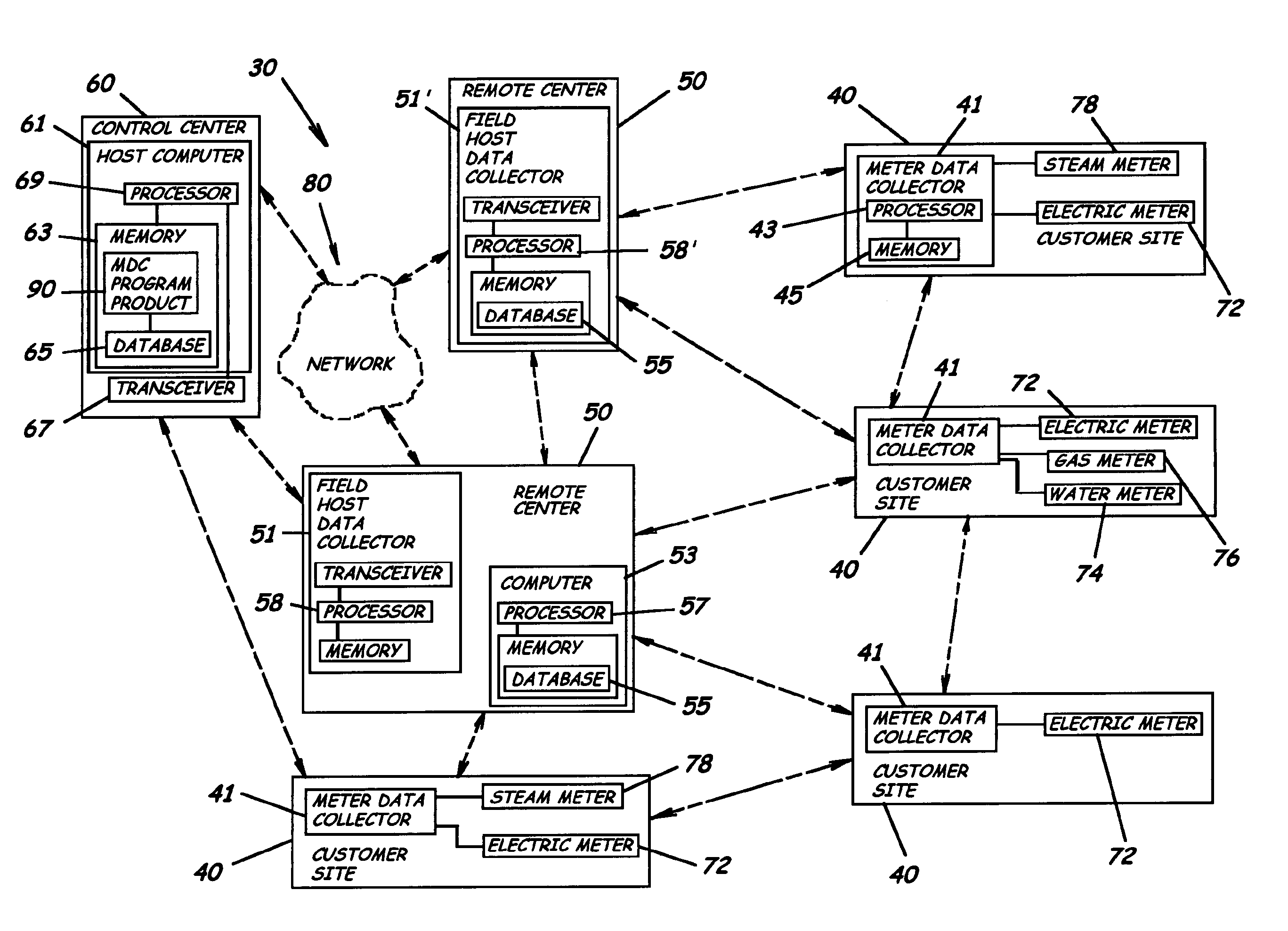
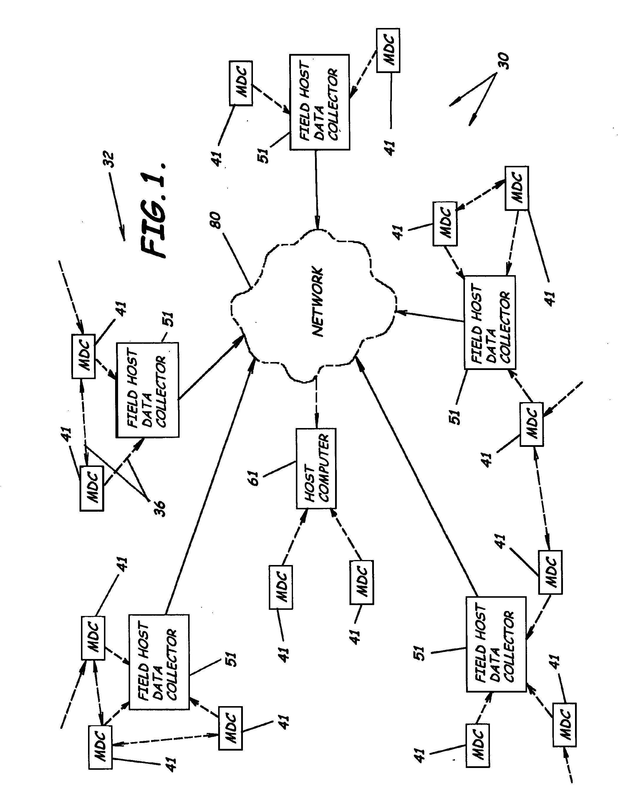
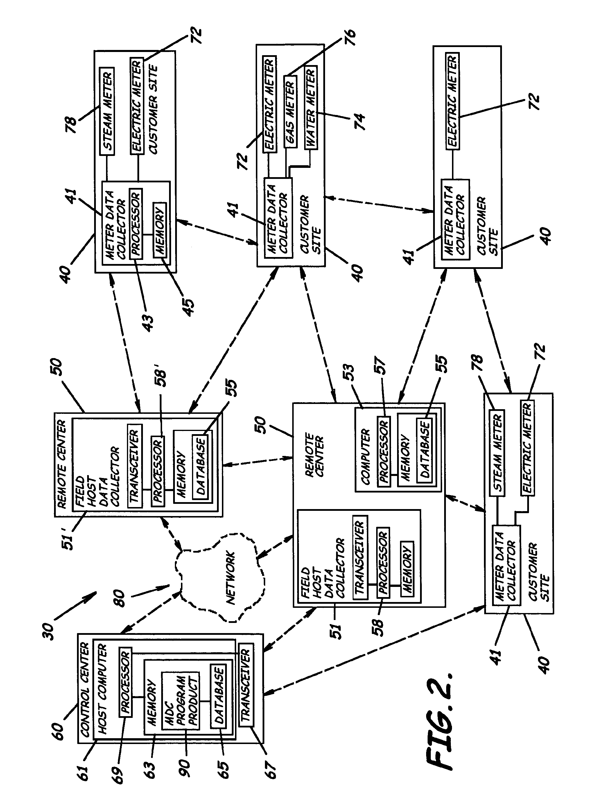
[0048] As illustrated in FIGS. 1-11, embodiments of the present invention incorporate an automated meter reading network system 30 that advantageously provides for both automated data acquisition and energy management. Generally, the automated meter reading network system 30 can support bi-directional communications with a network of meter data collectors 41 with the capa...


PUM


Abstract

An automated meter reading network system to collect utility usage data from multiple utility meters having utility meter sensors is provided. The system includes multiple meter data collectors each in communication with one or more utility meters to collect utility usage data and forming a wireless mesh communications network characterized by having a varying frequency mode of operation. The system also includes a host computer in communication with the meter data collectors either directly or through multiple field host data collectors, which can be connected to the host computer through a wide area network. The system also includes a meter data collector program product at least partially stored in the memory of the host computer adapted to manage the mesh communication network that is adapted to vary the frequency mode of at least portions of the mesh communication network between a fixed frequency mode and a frequency hopping spread spectrum mode to enhance network performance.

Description

RELATED APPLICATIONS [0001] This application is a continuation-in-part of and claims the benefit of U.S. patent application Ser. No. 10 / 779,429 filed on Feb. 13, 2004, which claims the benefit of U.S. application Ser. No. 60 / 447,815, filed on Feb. 14, 2003, both of which are incorporated herein by reference in their entirety.BACKGROUND [0002] 1. Field of the Invention [0003] The present invention relates in general to the field of utility meters. More particularly, the present invention relates to systems, automated equipment, networks, program products, and related methods for remote reading of utility meters. [0004] 2. Description of Related Art [0005] Utility companies and municipalities for many years have been burdened with the labor intensive and cumbersome task of manually collecting meter readings, managing data from the field into the accounting area, and managing the billing and collection of invoices. Typically each customer is provided with a mechanical utility meter for...

Claims


Application Information

Patent Timeline
IPC IPC(8): G08B23/00G08C15/06H04Q9/00
CPCH04Q9/00H04Q2209/25H04Q2209/60
Inventor BOAZ, JON A.
Owner ENERGY TECH GROUP
Why Eureka
Try Eureka