
Radar detector and radar detecting method for WLAN systems according to 802.11 wireless communication standards

Active Publication Date: 2005-12-08
WIPRO LTD
View PDF13 Cites 45 Cited by
  • Summary
  • Abstract
  • Description
  • Claims
  • Application Information

AI Technical Summary

Benefits of technology

[0008] It is the objective of the present invention to provide a radar detector and a radar detecting method for WLAN systems according to 802.11 wireless communication standards which considerably reduces the rate of error detections without degrading the detection rate.
[0011] In terms of objectives, we seek to achieve the following things: Detect the presence of any radar operating in the channel of interest in a quiet period, Assert that the radar is up and running upon processing a single pulse, Have a low rate of false alarm, Integrate the radar detection with the normal 802.11 a packet detection procedure.
[0013] However, from a practical standpoint, it is easier to calculate a scalar product between the received phase vector and a fitted model of it.

Problems solved by technology

The previous radar detector implemented in WLAN systems was solely based on the detection (power-wise) of a single short pulse and is expected to yield a relatively high rate of false alarm when performance assessment occurs.

Method used


Image

  • Radar detector and radar detecting method for WLAN systems according to 802.11 wireless communication standards
  • Radar detector and radar detecting method for WLAN systems according to 802.11 wireless communication standards
  • Radar detector and radar detecting method for WLAN systems according to 802.11 wireless communication standards

Examples


Embodiment Construction

[0016] Two schemes are available depending on the nature of the received radar pulse:

a. Sinusoidal Pulse Detector:

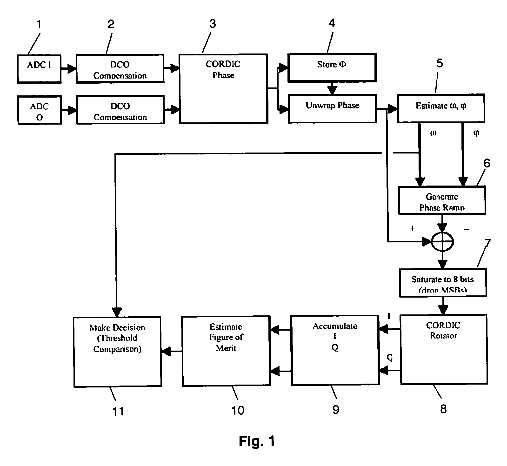
[0017] The sinusoidal radar detector of FIG. 1 is based on the fact that any sinusoidal function is fully characterized by two parameters phase-wise: Its angular frequency, Its initial phase.

[0018] Hence, the phase model for the sinusoidal pulse is an affined line whose slope and intersection with the phase axis respectively correspond to the angular frequency and initial phase just mentioned. In a nutshell, once a ramp up detection occurs (because a considerable signal is present in the frequency band), a short sample of the incoming signal is acquired and DC offset compensated. In a preferred implementation, thirty two (32) 60-MHz samples of I- and Q signals are captured and converted by analog-to-digital converters (Block 1) to digital signals. A coarse estimate of the DC offset is available thanks to a digital RSSI block (usually present in a WLAN receiver) where...


PUM


Abstract

The present invention relates to a radar detector and a radar detecting method for WLAN systems according to 802.11 wireless communication standards, and particularly concerns the radar detection for 802.1 l h dynamic frequency selection mechanism. The essence of the innovation consists in projecting the received phase vector on the signal subspace orthogonal to the expected radar pulse subspace and taking the norm of the resulting vector. The closer the norm is to zero, the more likely the received signal is to be a radar pulse. The invention is able to detect both, sinusoidal radar signals and chirp-like radar signals.

Description

FIELD OF THE INVENTION [0001] The present invention relates to a radar detector and a radar detecting method for WLAN systems according to 802.11 wireless communication standards, and particularly concerns the radar detection for 802.11h dynamic frequency selection mechanism. BACKGROUND OF THE INVENTION [0002] The wireless 802.11h communication standard, which is an extension of the 802.11 a standard, is designed to meet European regulations regarding the use of the 5 GHz band by ensuring that WLAN systems operating in this band do not interfere with military radars and other users of the frequency band. Two mitigation technologies are provided with that purpose in mind: Dynamic Frequency Selection (DFS): Transmit Power Control (TPC). [0003] The previous radar detector implemented in WLAN systems was solely based on the detection (power-wise) of a single short pulse and is expected to yield a relatively high rate of false alarm when performance assessment occurs. This scheme, which ...

Claims


Application Information

Patent Timeline
IPC IPC(8): G01S7/02G01S7/36G01S7/40H04L12/28H04W16/14
CPCH04W16/14G01S7/021
Inventor CHIODINI, ALAIN
Owner WIPRO LTD
Learn More