Flat wide-angle objective

a wide-angle objective and flat technology, applied in the field of flat wide-angle objectives, can solve the problems of inconvenient use and storage, increased overall radius and hence the dimension of the lens system, and achieve the effect of reducing the overall dimension

Inactive Publication Date: 2005-12-08
MICROALIGN TECH
View PDF5 Cites 41 Cited by
  • Summary
  • Abstract
  • Description
  • Claims
  • Application Information

AI Technical Summary

Benefits of technology

[0025] It is an object of the invention to further reduce overall dimensions of a flat wide- angle lens objective composed of a set of microlens arrays with a set of only two traditional lenses. It is another object to provide the aforementioned flat wide- angle lens objective that provides the same image quality as the known objective of this type with four traditional optical lenses. A further object is to provide a substatially flat objective that can be matched with CMOS, CCD, etc., and that can be integrated in an image-sensor camera module.
[0026] A flat wide-angle lens system of the invention is intended for creating images with extremely wide angle of observation. The wide-angle lens system consists of two main sub-units, i.e., a first sub-unit that is located on the object side of the objective that comprises an assembly of two conventional negative aspheric lenses, e.g., negative aspheric lenses having their flat sides facing the object, and a second sub-unit, i.e., a set of four microlens arrays arranged on the image- receiving side of the objective and having the same pitch between the adjacent microlenses. More specifically, the set of microlenses comprises a pair of identical microlens arrays, the first micro lens array and the second microlens array, interposed one onto the other with a diaphragm array sandwiched between the aforementioned first and second microlens arrays. The diaphragm array comprises a light-impermeable matrix with micro-openings of a predetermined diameter and with the same pitch as the aforementioned first and second microlens arrays. The diaphragm array may be made replaceable or may be applied as a permanent mask onto one of the aforementioned microlens arrays. The aforementioned set of microlens arrays further comprises a pair of additional identical microlens arrays, i.e., a third microlens array and a fourth microlens arrays. The third and fourth microlens arrays are located on opposite sides of the aforementioned sandwich and are equally spaced from the first and second microlens arrays, respectively. The objective described above may have an angle field (2ω) equal to about 60°. The objective of the invention can be realized into an optimal practical design only with predetermined relationships between the parameters of the optical system that forms the objective. The invention makes it possible to significantly reduce longitudinal dimension of the objective.

Problems solved by technology

In a lens system, aberration is an error resulting from a failure of light rays from one point to converge to a single focus.
Normally, conventional wide-angle photographic objectives or lens systems have big dimensions, i.e., a lengthy objective, and therefore are inconvenient for use and storage.
This not only increases the overall radius and hence the dimension of the lens system but also significantly increase the weight of the objective as a whole.
A common problem associated with wide-angle lens systems of the types described above as well as with other conventional wide-angle lens systems is that an increase in the aperture ratio of the lens system, widening of the field of observation, and improvement in resolution capacity of the optical system require an increase in the lens diameter.
However, such an increase leads to more noticeable aberrations, and in order to solve the aberration problem, it is necessary to introduce into the system new optical elements.
However, Increasing the number of lens elements to overcome the above-described drawbacks degrades the performance of the lens system due to adverse effects such as flare.
All this significantly increases the manufacturing cost and the cost of the products.
Nevertheless, while preserving the traditional structure, the lens optical system of U.S. Pat. No. 6,545,82 still remains large in size, heavy in weight, and complicated in structure.
These problems will always remain until a wide-angle lens system is designed on traditional principles of wide-lens system architecture.
It is understood that objectives of traditional design, i.e., those that use conventional three- dimensional optical lenses, cannot be reduced to the dimensions of a digital- camera objective without the loss of quality.
If one reviews the situation on the present market of megapixel cameras, it can be seen that in this technique the amount of pixels that can be used for obtaining an image is rapidly growing from month to month while matching of the growing megapixel capacity of the objective with the optical components without the loss of image quality becomes more and more problematic.
However, such results were achieved due to the use of traditional optical lenses having a very complicated shape with variable-sign curvatures on the same surface of the lens.
It is understood that manufacture of such lenses requires the use of complicated non-trivial technology.
With further increase in the pixel capacities of the CCD's or CMOS's the aforementioned manufacturing solution may confront some limitations from the side of optical component quality, especially if one tries to make the optics flat.
In principle, the objective described in U.S. patent application Ser. No. 10 / 862,178 can be realized with the use of only two or three conventional lenses but this could be done at the expense of the image quality that will be impaired because of aberration that could not be completely eliminated.

Method used


Image

  • Flat wide-angle objective
  • Flat wide-angle objective
  • Flat wide-angle objective

Examples


Embodiment Construction

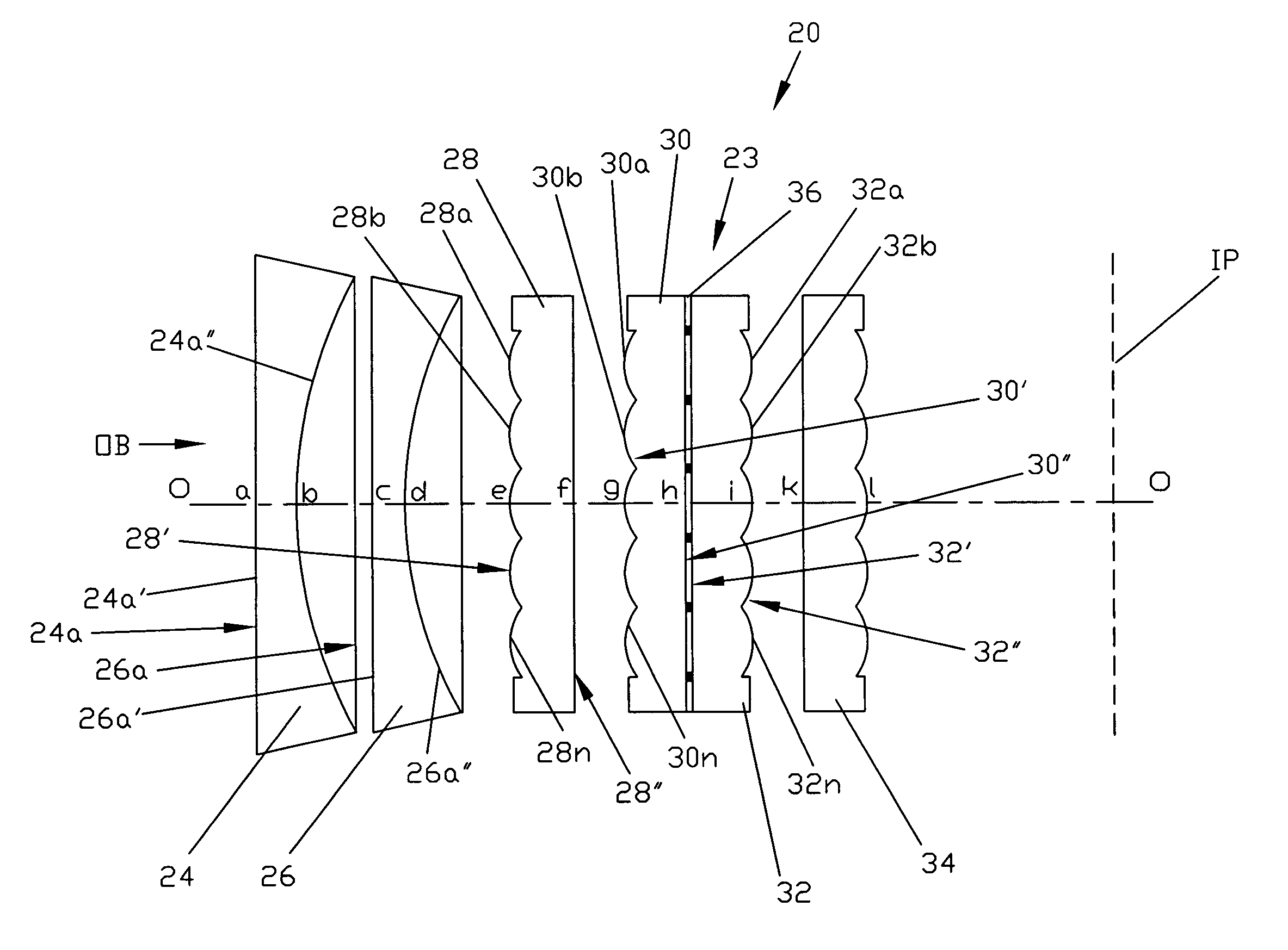
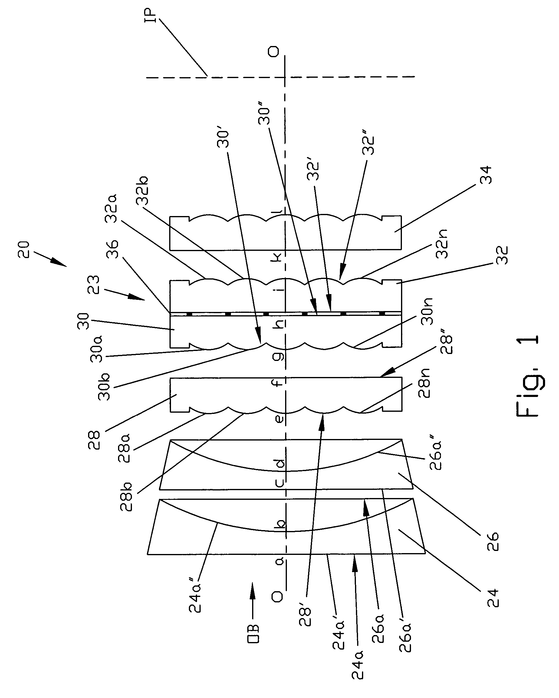
[0037] A flat wide-angle lens system of the invention, which herein after will be referred to as an objective of the present invention, is shown in FIG. 1 which is a general longitudinal sectional view of the aforementioned objective. The objective of the invention as a whole is designated by reference numeral 20. The objective 20 consists of two sub-assemblies. The first sub-assembly 22 that is located on the object side OB, which is on the left side in the view of FIG. 1, comprises an assembly of two conventional negative aspheric lenses 24 and 26, having their flat sides 24a and 26a, respectively, facing the object side OB. The second sub-assembly 23 is a set of four microlens arrays 28, 30, 32, and 34 arranged on the image-receiving side IP, which is on the right side of the view of FIG. 1. Reference numeral 36 designates a diaphragm array, which will be described later in consideration of the second sub-assembly 23.

[0038] Now the aforementioned sub-assemblies 22 and 23 of the ...


PUM


Abstract

A flat wide-angle objective of the invention consists of a first sub-unit that is located on the object side of the objective and comprises an assembly of two conventional aspheric negative, e.g., aspheric piano-concave lenses, and a second sub-unit in the form of a set of four microlens arrays arranged on the image-receiving side of the objective. The microlenses of all microlens arrays have the same arrangement of microlenses in all the arrays. A diaphragm array with restricting openings can be sandwiched between a pair of the microlens arrays. The objective of the invention can be realized into an optimal design only with predetermined relationships between the parameters of the optical system that forms the objective. The invention makes it possible to drastically reduce longitudinal dimension of the objective. In operation, the first sub-unit creates an imaginary image of the object in its focal plane, which is located on object side of the objective, while the second sub-unit creates an actual image of the object in the image plane on the image-receiving side of the objective. In this case, the function of the object plane is fulfilled by the aforementioned focal plane of the first sub-unit that contains the imaginary image of the real object.

Description

CROSS-REFERENCE TO RELATED APPLICATIONS [0001] The present patent application is a continuation in part of U.S. patent application Ser. No. 10 / 862,178 filed by the same applicants on Jun. 7, 2004 and entitled “Flat Wide-Angle Lens System”.FIELD OF THE INVENTION BACKGROUND OF THE INVENTION [0002] The present invention relates to the field of optics and, more particularly, to a wide-angle flat photographic lens objective. More specifically, the invention relates to a wide-angle flat photographic lens system which is built on an entirely new principle of combining a group or groups of flat microlenses with a group or groups of conventional optical lenses. The lens system of the invention may find application in photographic cameras, image projection systems, etc. BACKGROUND OF THE INVENTION [0003] For better understanding the terminology used in the present description and principles of structure of optical systems in general, it would be advantageous to make some short introduction in...

Claims


Application Information

Patent Timeline
Patent Type & Authority Applications(United States)
IPC IPC(8): G02B3/00G02B9/00G02B9/60G02B13/04G02B13/06G02B13/18
CPCG02B3/0056G02B3/0068G02B13/06G02B13/18
Inventor GUREVICH, IGORFAYBISHENKO, VICTORVELIKOV, LEONID
Owner MICROALIGN TECH
Why Eureka
Try Eureka