
Sound signal wire and process for enhancing rigidity thereof

a technology of sound signal wire and rigidity, which is applied in the direction of transducer details, basic electric elements, electrical transducers, etc., can solve the problems of short circuit of sound signals, serious damage, and ineffective cost-effective process of fabricating speakers, and achieve the effect of eliminating the occurrence of roping effect and high rigidity

Inactive Publication Date: 2005-12-08
TAIWAN MAEDEN
View PDF8 Cites 9 Cited by
  • Summary
  • Abstract
  • Description
  • Claims
  • Application Information

AI Technical Summary

Benefits of technology

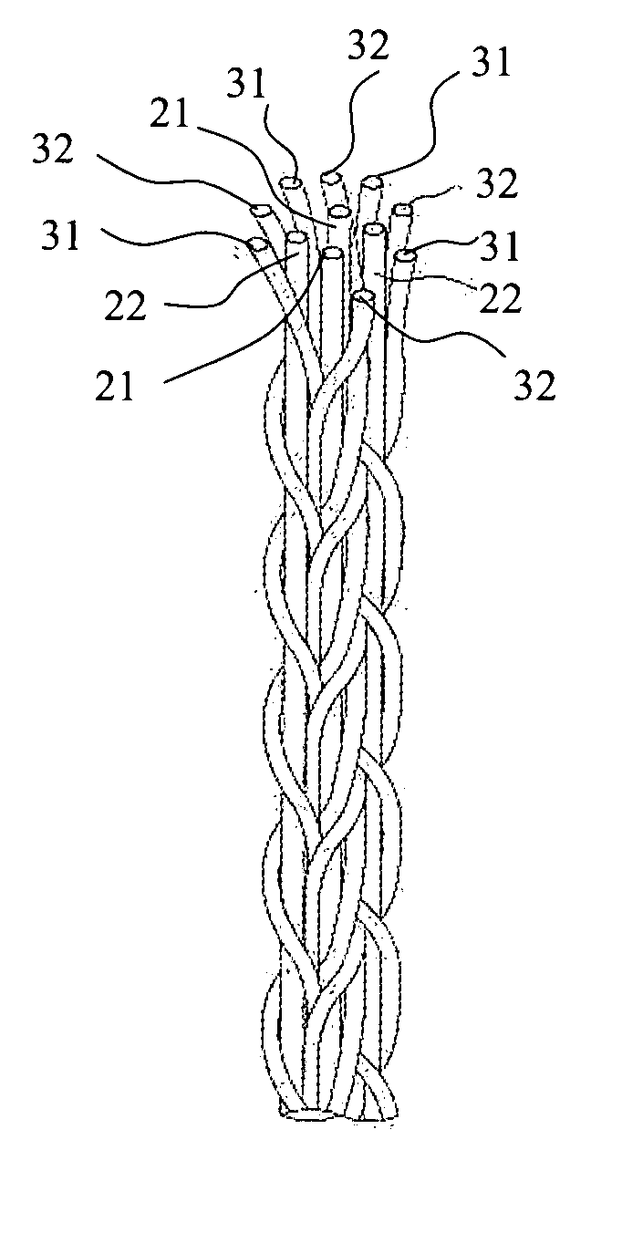
[0010] A primary objective of the present invention is to provide a sound signal wire that connects between a speaker sound input port and a speaker diaphragm, in which the wire is formed by a specific weaving arrangement to allow for higher rigidity which eliminates the occurrence of a roping effect under high-frequency and / or long-lasting vibrations. This sound signal wire is formed by furnishing two groups of wires, wherein the first group of wire units forms a support, and the second group of wire units forms a set of peripheral wires weaving in respect to the support wire units.
[0011] Another objective of the invention is to provide a sound signal wire that has a greater tensile strength and a more durable service life, in which each of the wire units constituting the signal wire includes an inner fiber that is made of a super heat-resistant fiber formed by mixed-weaving a poly para-aramid fiber and a poly meta-aramid fiber.
[0012] A further objective of the invention is to provide a sound signal wire, in which the wire is dipped in a solution of acetal resin or polyurethane to form a coating on the surface of the wire, thereby increasing the wire rigidity and avoiding the roping effect under the intense vibration of the speaker.
[0013] Yet a further objective of the invention is to provide a sound signal wire with the combination of (1) providing the foregoing inner fiber encompassed by a conductive metal sheet as each of the wire units, (2) furnishing two groups of wire units and weaving them into the signal wire, and finally (3) dipping the wire in a specific solution to form an end product that has a relatively high rigidity without the occurrence of the undesired roping effect, and improving the tensile strength, flexibility and durability thereof.

Problems solved by technology

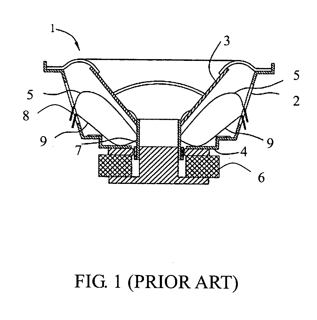
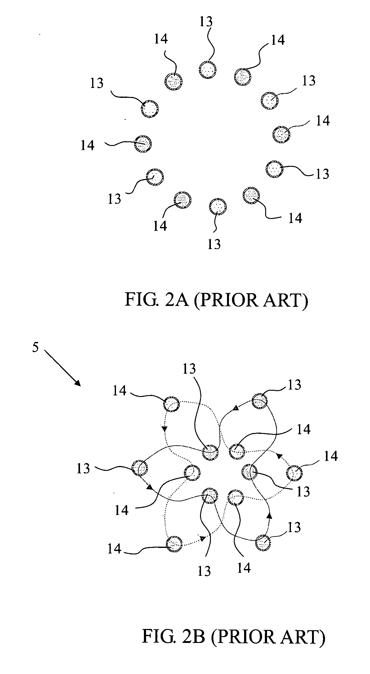
This undesired effect may also cause the sound signal wires to come into contact with each other, producing a short-circuiting of the sound signals.
Even worse, the roping effect may cause the sound signal wires to strike the diaphragm 3 or damper 4, resulting in some serious damage.
The foregoing arrangement of replacing sound signal wires by coating the conductive metal layer on the damper or fixing the sound signal member on the damper would make processes of fabricating a speaker more complicated and cost-ineffective.
Moreover, operational inaccuracy or imprecision may easily degrade transmission quality of sound signals.

Method used


Image

  • Sound signal wire and process for enhancing rigidity thereof
  • Sound signal wire and process for enhancing rigidity thereof
  • Sound signal wire and process for enhancing rigidity thereof

Examples


preparation of example 1

[0035] Poly meta-phendioyl meta-phenylene diamide is used as a textile material for an inner fiber. The inner fiber is made with its specification of a 40-in-2 strand (wherein the “40-in-2” means that the diameter of each of the 2 strands is 40 Ne) and encompassed by a single sheet of copper foil coated with silver to form a wire unit. Then, 7 strands of the wire units are wound and then subjected to anti-oxidation treatment at 82° C. to form Sample 1 of the sound signal wire.

preparation of example 2

[0036] The formation of Sample 2 of the sound signal wire similarly follows the above process of Preparation Example 1, except that the inner fiber is encompassed by two sheets of copper foil coated with silver to form the wire unit.

preparation of example 3

[0037] The formation of Sample 3 of the sound signal wire similarly follows the above process of Preparation Example 2 , except that the inner fiber is made with its specification of a 30-in-3 strand (wherein the “30-in-3” means that the diameter of each of the 3 strands is 30 Ne).


PUM


Abstract

A sound signal wire that has higher rigidity to prevent roping effect from reducing sound quality during vibration within a speaker frame, and / or also has a higher flexibility and tensile strength to make the vibrated sound signal wire more durable for use with a speaker for transmitting sound signals is disclosed. The sound signal wire is constructed from sets of weaving wire units which weave onto other sets of support wire units along specific paths, with acetal resin or polyurethane coating the surface of the wire. Each wire unit is comprised of an inner fiber and a conductive metal sheet encompassing the inner fiber, in which the inner fiber is a heat-resistant fiber that is made by a poly meta-aramid fiber mixed-woven with a poly para-aramid fiber.

Description

CROSS-REFERENCES TO RELATED APPLICATIONS [0001] This is a continuation-in-part application of U.S. patent application Ser. No. 10 / 318,007.STATEMENT REGARDING FEDERALLY SPONSORED RESEARCH OR DEVELOPMENT [0002] Not applicable. BACKGROUND OF THE INVENTION [0003] 1. Field of the Invention [0004] The present invention relates to sound signal wires, more specifically a sound signal wire that has a higher rigidity to prevent roping effect from reducing its sound quality during vibration within a speaker frame, and / or a higher flexibility and tensile strength to make the vibrated sound signal wire more durable for use when transmitting sound signals within a speaker. [0005] 2. Descriptions of the Related Art [0006] With reference to FIG. 1, a typical speaker 1 includes a speaker frame 2, a diaphragm 3, a damper 4, sound signal wires 5, a magnet 6, magnetic circuits (not shown), a voice coil bobbin (not shown), and a voice coil 7 surrounding the voice coil bobbin. A sound signal is transmitt...

Claims


Application Information

Patent Timeline
Patent Type & Authority Applications(United States)
IPC IPC(8): H04R1/06
CPCH04R1/06
Inventor KO, JOSEPH
Owner TAIWAN MAEDEN
Learn More