Electrodeposition of FeCoNiV films with high resistivity and high saturation magnetization

a feconiv film, high resistivity technology, applied in the field of magnetic write head, can solve the problems of low resistivity of less than 20 ohms-cm, limit the high frequency application of films in magnetic recording head, and film usually has an unacceptably low bsub>s /sub>value, so as to achieve the effect of convenient implementation

Active Publication Date: 2005-12-08
HEADWAY TECH INC
View PDF13 Cites 16 Cited by
  • Summary
  • Abstract
  • Description
  • Claims
  • Application Information

AI Technical Summary

Benefits of technology

[0010] A further objective of the present invention is to provide a method of forming the improved magnetic layer according to the first embodiment which can easily be implemented in a magnetic head fabrication process.

Problems solved by technology

Unfortunately, electroplated FeCo or FeCoNi films that are generally used in the industry as top and bottom pole layers in a write head have a high Bs value but a relatively low resistivity of less than 20 μohms-cm which limits the high frequency application of the films in magnetic recording heads.
On the other hand, when an alternative film that has a high resistivity is employed as the top pole layer, the film usually has an unacceptably low Bs value.
However, the high specific resistance layer requires a protective layer to prevent cracking which increases the complexity of the fabrication process and is likely to drive up production cost.
Although a high Bs value is mentioned, the cited references do not teach a high Bs in combination with a high resistivity for pole layer applications in a write head.

Method used


Image

  • Electrodeposition of FeCoNiV films with high resistivity and high saturation magnetization
  • Electrodeposition of FeCoNiV films with high resistivity and high saturation magnetization
  • Electrodeposition of FeCoNiV films with high resistivity and high saturation magnetization

Examples


first embodiment

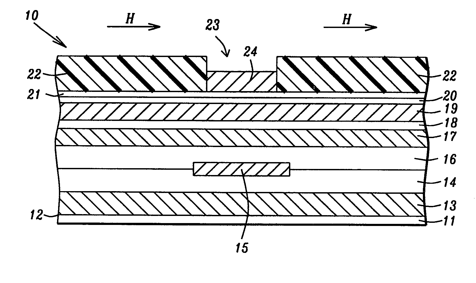
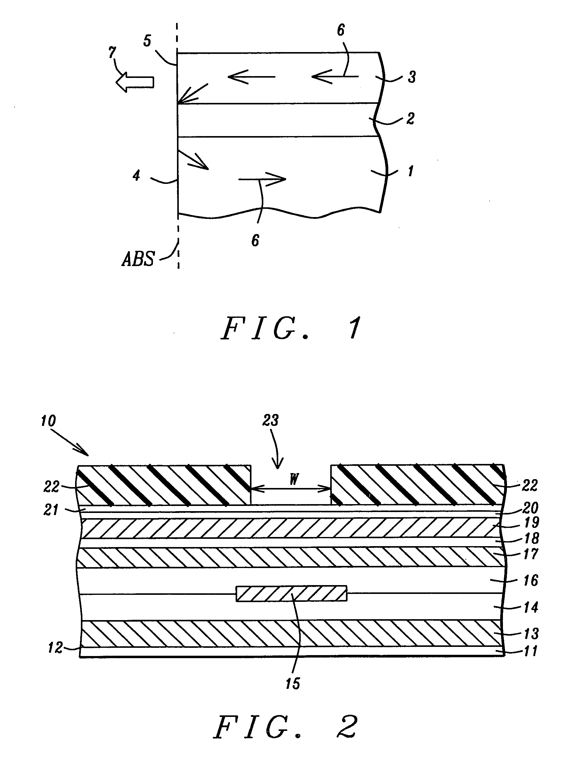
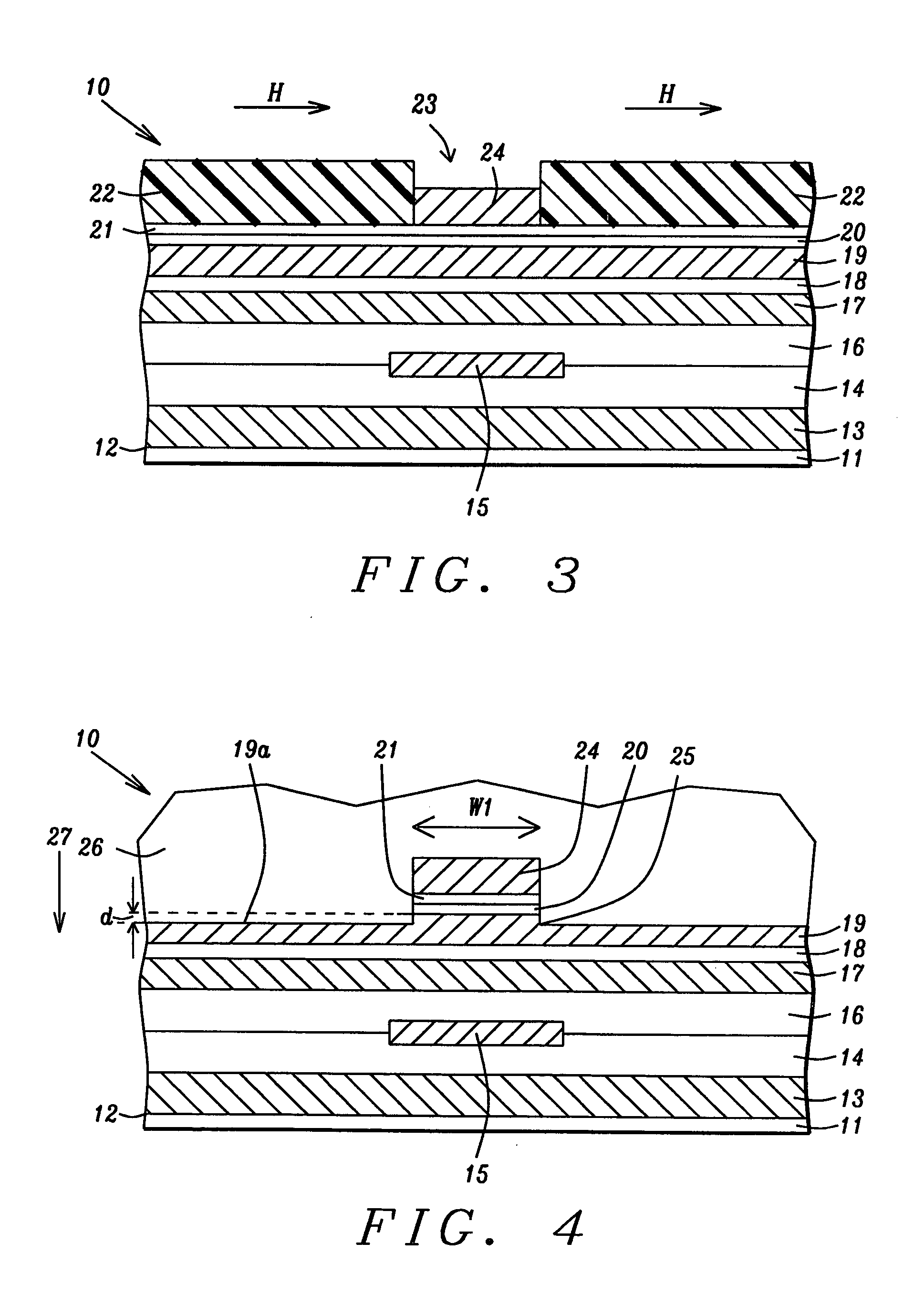
[0024] A first embodiment is depicted in FIGS. 2-4 and relates to a method of fabricating the magnetic layer of the present invention which is the top pole layer in a write head. The write head is shown as part of a separated read-write head structure but is not limited thereto. Referring to FIG. 2, a partially formed read-write head 10 that is part of a magnetic disk drive is shown as viewed from the plane of an ABS.

[0025] The read head portion of the read-write head 10 is comprised of a substrate 11 that may be a ceramic such as AlTiC. The substrate 11 has a top surface 12 that is perpendicular to the ABS. A first shield layer 13 is formed on the substrate 11. Above the first shield layer 13 is sequentially formed a first insulation layer 14 and a second insulation layer 16 with a sensor element 15 formed therein along an interface between the first and second insulation layers which are made of Al2O3 or silicon oxide, for example. The sensor element 15 is preferably based on a gi...

second embodiment

[0034] In a second embodiment illustrated in FIGS. 5-7, the magnetic layer according to the present invention is used as a bottom pole layer and a top pole layer in a write head. Although a separated read-write head structure is shown, the write head is not limited thereto. A method of forming the magnetic layer of the present invention will now be described.

[0035] Referring to FIG. 5, a cross-sectional view from an ABS is shown of a read-write head 30 which is comprised of a substrate 31 that may be a ceramic such as AlTiC. The substrate 31 has a top surface 32 that is perpendicular to the ABS. A first shield layer 33 is formed on the substrate 31. Above the first shield layer 33 is sequentially formed a first insulation layer 34 and a second insulation layer 36 with a sensor element 35 formed therein along an interface between the first and second insulation layers. The sensor element 35 is preferably based on a giant magnetoresistive (GMR) configuration comprised of a pinned laye...


PUM

PropertyMeasurementUnit
thicknessaaaaaaaaaa
coercive fieldaaaaaaaaaa

Abstract

A magnetic layer that may serve as a top pole layer and bottom pole layer in a magnetic write head is disclosed. The magnetic layer has a composition represented by FewCoxNiyVz in which w, x, y, and z are the atomic % of Fe, Co, Ni, and V, respectively, and where w is between about 60 and 85, x is between about 10 and 30, y is between 0 and about 20, z is between about 0.1 and 3, and wherein w+x+y+z=100. An electroplating process having a plating current density of 3 to 30 mA/cm2 is used to deposit the magnetic layer and involves an electrolyte solution with a small amount of VOSO4 which is the V source. The resulting magnetic layer has a magnetic saturation flux density Bs greater than 1.9 Telsa and a resistivity ρ higher than 70 μohms-cm.

Description

FIELD OF THE INVENTION [0001] The invention relates to a magnetic write head and to a method for making the same and in particular to a magnetic layer with high resistivity and high magnetic flux density for high frequency operations that can serve as a pole layer in an inductive write head. BACKGROUND OF THE INVENTION [0002] A magnetic disk drive includes a rotating magnetic disk with circular data tracks and magnetic read and write elements in which a write head is typically aligned with (or to) a read head on a slider. During a recording operation, the slider positions the read head and write head which are suspended over the magnetic disk on an air bearing surface (ABS). The write head has bottom and top pole layers that are connected at a back gap region. The bottom and top pole layers each have pole tips that are separated by a write gap layer and terminate at the ABS. In a merged read-write head configuration, the bottom pole also serves as the second shield layer in the read...

Claims


Application Information

Patent Timeline
Patent Type & Authority Applications(United States)
IPC IPC(8): C22C38/00B05D5/12C25D3/56G11B5/187G11B5/265G11B5/29G11B5/31G11B5/39H01F10/16H01F41/26
CPCC25D3/562G11B5/187G11B5/31G11B5/3116C22C38/10Y10T428/11G11B5/1877G11B5/3133Y10T428/1121Y10T428/115Y10T428/1193C22C38/12
Inventor LI, FEIYUELIU, XIAOMIN
Owner HEADWAY TECH INC
Why Eureka
Try Eureka