Fuel cell stack with even distributing gas manifolds

Inactive Publication Date: 2005-12-08
HYTEON
View PDF77 Cites 34 Cited by
  • Summary
  • Abstract
  • Description
  • Claims
  • Application Information

AI Technical Summary

Benefits of technology

[0016] It is therefore the primary objective of the present invention to provide a gas manifold design that provides uniform flow to each cell in the stack. It is important that the manifold design according to the present invention should work equally well for the pure hydrogen (dead-ended operation) and reformate (continuous operation) at either low or high pressures.
[0017] According to a first broad aspect of the present invention, there is provided a method of controlling fluid flow to a stack of fuel cell flow field plates, the method comprising providing in each fuel cell flow field plate of the stack of plates a fluid supply manifold aperture for conducting a supply of fluid to a number of the plates in the stack, the fluid supply manifold apertures forming an elongated fluid supply manifold extending through the stack; flowing the supply of fluid into the fluid supply manifold; laterally diverting a part of the supply of fluid to feed each of the number of the plates, wherein the number of the plates are each fed in parallel from the fluid supply manifold, and the laterally diverting is performed in a manner to avoid turbulence in the fluid supply manifold from

Problems solved by technology

External manifolds are simpler and less costly to manufacture than internal manifolds, but have major drawbacks, such as gas leakage and sealing problems.
However, current designs, regardless of whether their shape is rounded-rectangular or irregular, have been found to provide too low of a flow to a certain number of the cells near the manifold inlet or outlet or at both ends, which results in cell starvation and poor water management.
In addition, non-uniform distribution encourages use of large reactant supply rates (large stoichiometry) thus resulting in low reactant utilization and large parasitic power consumption.
Unfortunately, the addition of the transit manifolds would, however, increase the requirement for sealing, and create extra pressure losses.
In addition, the disclosed method does not provide a uniform flow to the upstream flow passages of the first transit manifold, which would pose a serious problem because the upstream part, where the electrochemical reactions generally undergo vigorously, will have a significant impact on the cell performance.
The position of the piercing is, however, difficult to maintain accurately during stack assembly and throughout the lifetime of the fuel cell.
Furthermore, it is hard to achieve a developed flow after the gas passing the piercing, which in general would have caused more turbulence and even wake flow that certainly will result in non-uniform flow distributions into the cells and into the channels communicating with the manifold.
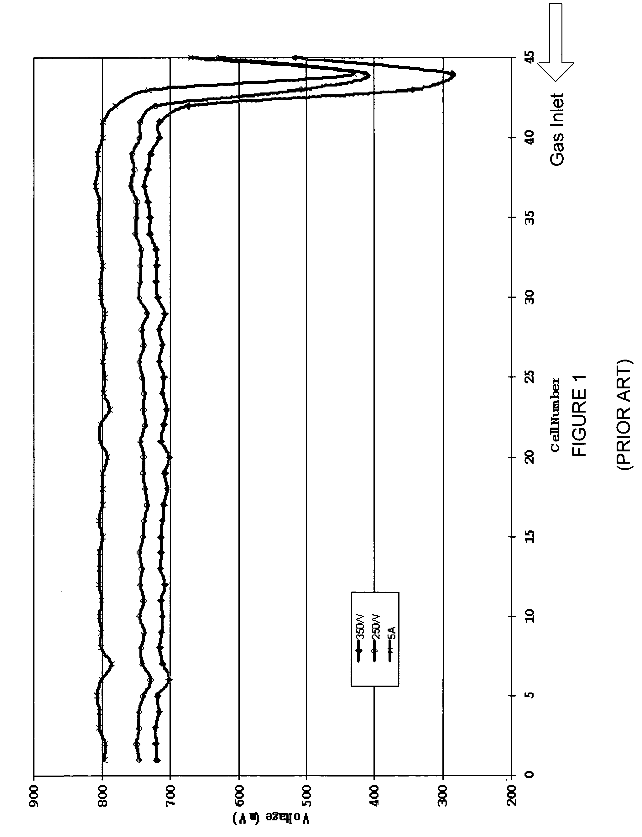
It has been observed that the fuel cell stack exhibits no

Method used


Image

  • Fuel cell stack with even distributing gas manifolds
  • Fuel cell stack with even distributing gas manifolds
  • Fuel cell stack with even distributing gas manifolds

Examples


Example

[0031] Preferred embodiments of the present invention will be described in detail hereinafter with reference to the accompanying drawings FIG. 5 to FIG. 9.

[0032] Referring to FIG. 5, a fuel cell stack 10 is structured according to the present invention by stacking a plurality of unit cells 200 repeatedly between an end plate 20 and another end plate 30. As shown in FIG. 5, an assembly comprising of a membrane electrode assembly (MEA) and integrated GDL and gasket 40 is sandwiched between an anode plate and a cathode plate. On each plate there is a first manifold hole 110, which preferably has the same shape and size as the hole 110 on the end plate 20. The first manifold hole 110 receives and transports the gas supply from the external gas supplying line 100. By having the geometry of the manifold holes 110 on the plates match the holes 110 on the end plate 20, the change in gas flow pattern due to geometric variation between supplying line and manifold entrance will be eliminated ...


PUM


Abstract

A method of controlling fluid flow to a stack of fuel cell flow field plates comprises providing in each fuel cell flow field plate of the stack of plates a fluid supply manifold aperture for conducting a supply of fluid to a number of the plates in the stack, the fluid supply manifold apertures forming an elongated fluid supply manifold extending through the stack, flowing the supply of fluid into the fluid supply manifold and laterally diverting a part of the supply of fluid to feed each of the number of the plates. The plates are each fed in parallel from the fluid supply manifold, and the laterally diverting is performed in a manner to avoid turbulence in the fluid supply manifold from adversely affecting supply of fluid to downstream ones of the number of plates.

Description

CROSS-REFERENCE TO RELATED APPLICATIONS [0001] The application is related to commonly assigned co-pending U.S. patent application titled “Flow Field Plate for Use in Fuel Cells”, filed simultaneously herewith and bearing agent docket number 16961-1US, the content of which is hereby incorporated by reference.STATEMENT REGARDING US GOVERNMENT SPONSORED RESEARCH OR DEVELOPMENT [0002] Not Applicable. FIELD OF THE INVENTION [0003] The invention relates to a gas separator for use in a fuel cell. More specifically, it relates to a method and apparatus for controlling the distribution of reaction gases into unit cells in a fuel cell stack. BACKGROUND OF THE INVENTION [0004] Fuel cells are electrochemical devices that convert chemical energy from a fuel directly into electrical energy with high efficiency. Generally, a single Proton Exchange Membrane (PEM) fuel cell employs a membrane electrode assembly (MEA) that comprises an ion exchange membrane or solid polymer electrolyte disposed betwe...

Claims


Application Information

Patent Timeline
IPC IPC(8): H01M8/02H01M8/04H01M8/24
CPCH01M8/0258H01M8/04089H01M8/0263H01M8/2485H01M8/2483H01M8/241Y02E60/50H01M8/02H01M8/24
Inventor BAI, DINGRONGCHOUINARD, JEAN-GUYELKAIM, DAVID
Owner HYTEON
Why Eureka
Try Eureka