Stent delivery system

a technology of stent and inner member, which is applied in the field of medical devices, can solve the problems of limited control during deployment, difficult to maintain the position of the inner member, and the tendency of the stent to escape from the inner member, and achieve the effect of high degree of control

Inactive Publication Date: 2005-12-08
CR BARD INC
View PDF71 Cites 137 Cited by
  • Summary
  • Abstract
  • Description
  • Claims
  • Application Information

AI Technical Summary

Benefits of technology

[0011] It is therefore an object of the invention to provide a stent delivery

Problems solved by technology

However, it is very difficult to maintain the position of the inner member while moving the outer member to deploy the stent.
As such, the degree of control during deployment is limited.
Under such limited control there is a tendency for the stent to escape from the inner member before the jacket is fully retracted and jump from the desired deployment site.
This may result in deployment of the stent at a location other than the desired implant site.
First, the handle is not particularly well suited to short stents as there is little fine control.
Second, the handle is not well-suited to long stents, e.g., up to 90 mm in length, as the linear control requires the operat

Method used


Image

  • Stent delivery system
  • Stent delivery system
  • Stent delivery system

Examples


Embodiment Construction

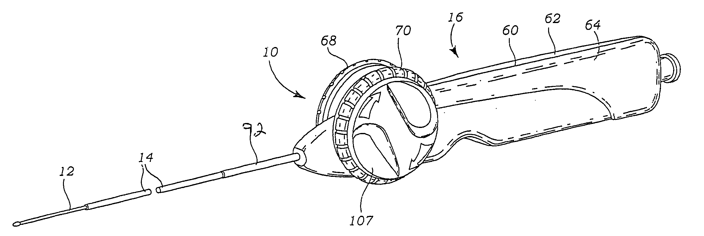
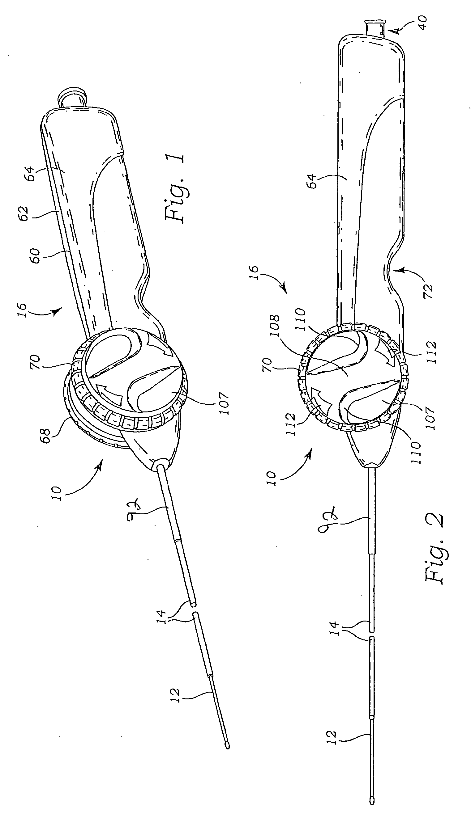
[0035] Referring now to FIGS. 1 and 2, a stent delivery system 10 generally includes an inner tubular member 12, a tubular jacket 14 slidable over the inner tubular member 12, and a handle 16 adapted to effect longitudinal movement of the jacket 14 relative to the inner tubular member 12.

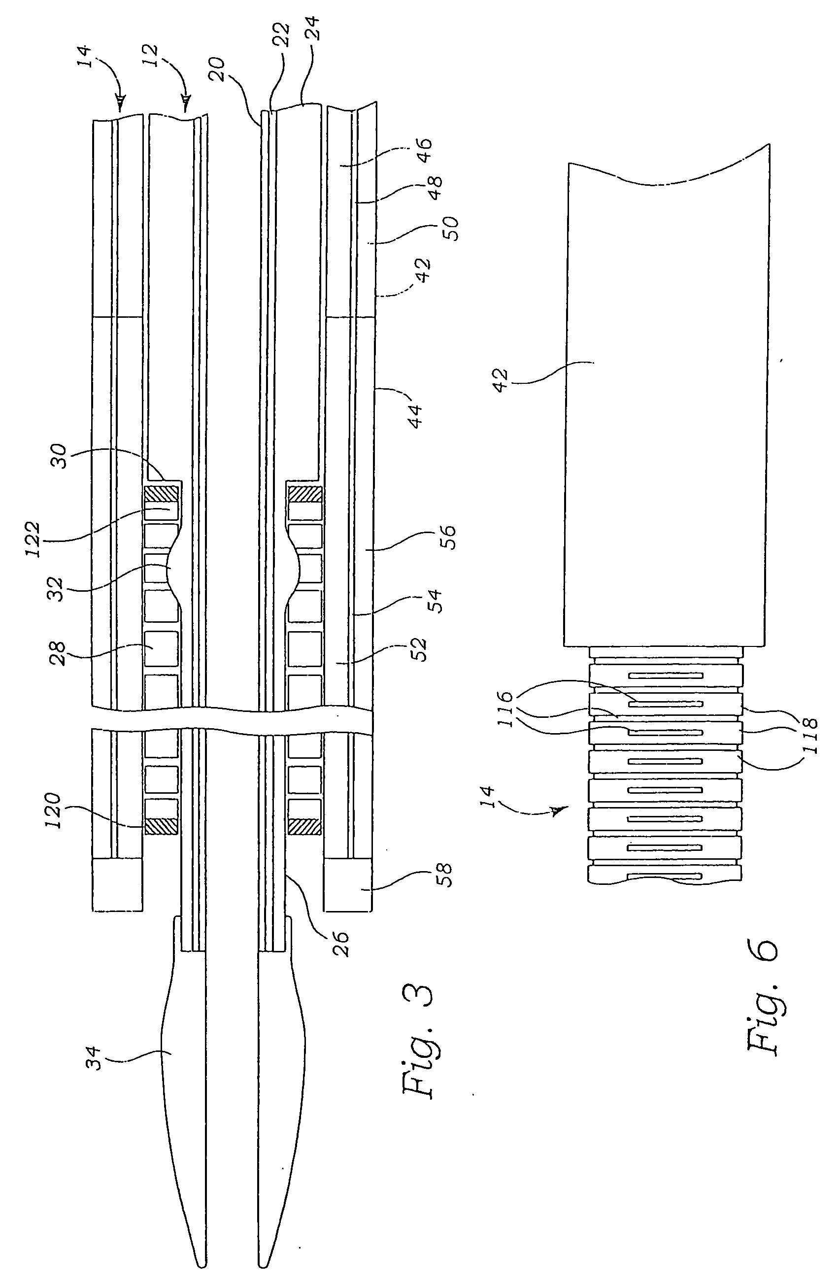
[0036] Turning now to FIG. 3, the inner tubular member 12 is preferably a coextruded, trilayer construction. The inner layer 20 is preferably polytetrafluoroethylene (PTFE), fluorinated ethylene propylene (FEP), high density polyethylene (HDPE), or urethane. The middle layer 22 is a wire braid, and more preferably a 304V stainless steel flat wire braid of 1×3 (40 picks) construction, with wires having a 0.001 inch by 0.003 inch rectangular cross-section. Wires of other metals and alloys may also be used, including other stainless steel alloys, cobalt-chrome alloys, and other high-strength, high-stiffness, corrosion-resistant metal alloys. The outer layer 24 is preferably a thermoplastic, melt proce...


PUM


Abstract

A stent delivery system includes an inner tubular member on which a stent is loaded, an outer jacket extending over said inner tubular member, the retraction of which causes deployment of the stent, and a handle adapted to move the jacket relative to the inner tubular member. The constructions of the inner tubular member and outer jacket and the handle provide increased control of the relative movement of the outer jacket relative to the inner tubular member, and prevention of premature release of the stent from the deployment instrument, and greater control over stent deployment among other advantages.

Description

CROSS-REFERENCE TO RELATED APPLICATIONS [0001] The present application claims priority to U.S. Provisional Application No. 60 / 577,300, filed on Jun. 4, 2004, the disclosure of which is incorporated herein by reference in its entirety for all purposes.FIELD OF INVENTION [0002] This invention relates broadly to medical devices. More particularly, this invention relates to an instrument for delivering a self-expanding stent into a mammalian body and controllably releasing the stent. BACKGROUND OF THE INVENTION [0003] Transluminal prostheses are widely used in the medical arts for implantation in blood vessels, biliary ducts, or other similar organs of the living body. These prostheses are commonly known as stents and are used to maintain, open, or dilate tubular anatomical structures. [0004] The underlying structure of the stent can be virtually any stent design. There are typically two types of stents: self-expanding stents and balloon expandable stents. Stents are typically formed fr...

Claims


Application Information

Patent Timeline
IPC IPC(8): A61F2/06A61F2/84
CPCA61F2002/9517A61F2/966A61F2002/9665A61F2/9517
Inventor FULKERSON, JOHNRANDALL, MICHAELJIMENEZ, TEODORO S. JR.
Owner CR BARD INC
Why Eureka
Try Eureka