Methods of Manufacturing Fluid-Dynamic-Pressure Bearing and Spindle Motor Incorporating the Bearing, and Spindle Motor and Recording-Disk Drive Incorporating the Bearing

a technology of fluid-dynamic pressure bearings and manufacturing methods, which is applied in the direction of recording information storage, magnetic circuit shape/form/construction, instruments, etc., can solve the problems of affecting and affecting the life of bearings. , to achieve the effect of improving the adhesion strength of spindle motors

Active Publication Date: 2005-12-15
NIPPON DENSAN CORP
View PDF10 Cites 21 Cited by
  • Summary
  • Abstract
  • Description
  • Claims
  • Application Information

AI Technical Summary

Benefits of technology

[0023] A first object of the present invention is to make available a manufacturing method that enables the adhesive strength in spindle motors to be improved.

Problems solved by technology

If the lubricating fluid is not sealed in by the capillary seal section, the fluid ends up leaking out to the exterior.
As a consequence, the lubricating fluid retained in the micro-gap runs short, ultimately curtailing the lifespan of the bearing.
In bearing implementations in miniature spindle motors in particular, since the gross amount of oil retained inside the bearing is very little, if even a slight amount of the lubricating fluid manages to leak out, an oil shortfall is liable to occur.
Furthermore, the problem of weak sealing performance in capillary seals can allow shock or other impact on the bearing to disturb the integrity of the seal boundary surface.
Nevertheless, the wettability of the oil repellant for the seal component surfaces is poor, which has meant that the repellant-to-surface adhesiveness has not been satisfactory.
Consequently, oil mop-up or associated concluding operations in manufacturing dynamic-pressure bearings cause the oil repellant to peel off easily.
Although processes such as striating the components or spreading the oil repellant on thickly have been implemented to date on account of the behavior of the repellant, such processes elevate the component cost, and, moreover, have not amounted to a fundamental solution.
The slightest warpage or deformation in spindle-motor bearing components becomes a problem particularly in fluid-dynamic-pressure bearings, in that the bearing gaps are extraordinarily narrow.
Especially under environments, such as in mobile and vehicular devices, that place vibration and shock on the bearings, particularly large loads are placed on the joints between components.
Consequent on the scaling down of spindle motors, however, is an abridgement of the inter-component binding length, which has made improving the binding strength a challenge.

Method used


Image

  • Methods of Manufacturing Fluid-Dynamic-Pressure Bearing and Spindle Motor Incorporating the Bearing, and Spindle Motor and Recording-Disk Drive Incorporating the Bearing
  • Methods of Manufacturing Fluid-Dynamic-Pressure Bearing and Spindle Motor Incorporating the Bearing, and Spindle Motor and Recording-Disk Drive Incorporating the Bearing
  • Methods of Manufacturing Fluid-Dynamic-Pressure Bearing and Spindle Motor Incorporating the Bearing, and Spindle Motor and Recording-Disk Drive Incorporating the Bearing

Examples


first embodiment

[0066] In the present embodiment, a fluid-dynamic-pressure bearing for which a manufacturing method of the present invention is utilized is employed in a spindle motor 3 that spins discoid recording media.

[0067] Hard-Disk Drive

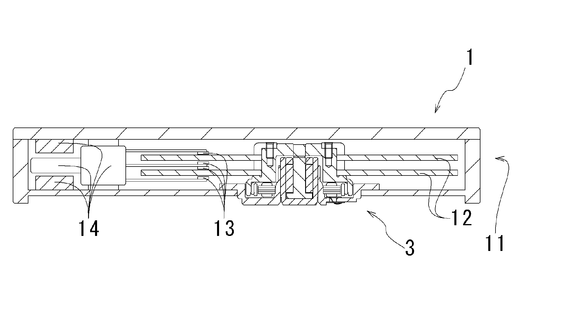
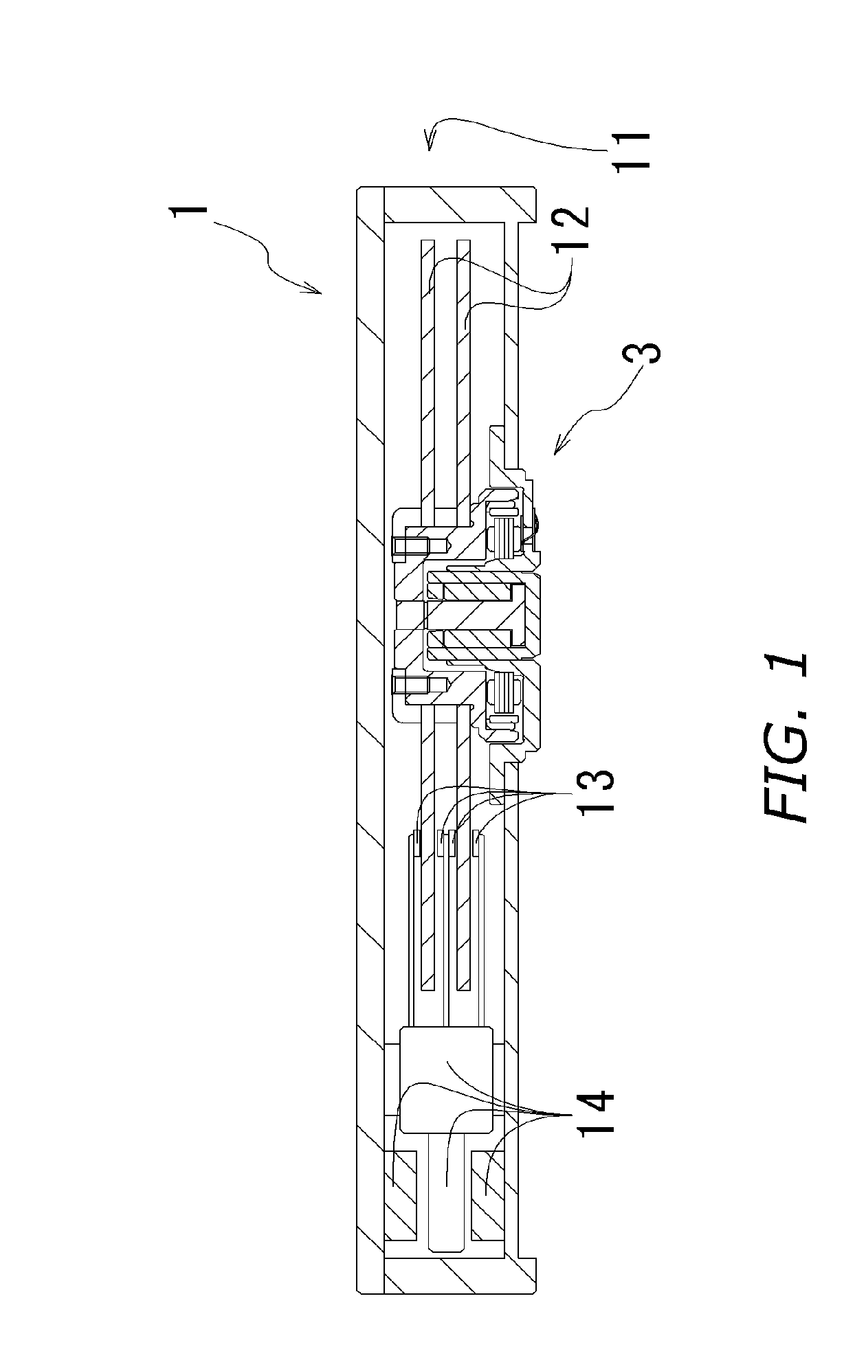
[0068] Reference is made to FIG. 1, which is a sectional view illustrating a hard-disk drive 1 that is a recording-disk drive device embodying the present invention. The hard-disk drive 1 is in the interior of a case 11 furnished with a spindle motor 3 that spins recording disks 12, heads 13 that read information from and write information into the recording disks 12, and an actuator unit 14 that shifts the heads 13 into select locations over the recording disks 12.

[0069] Spindle Motor Configurational Outline

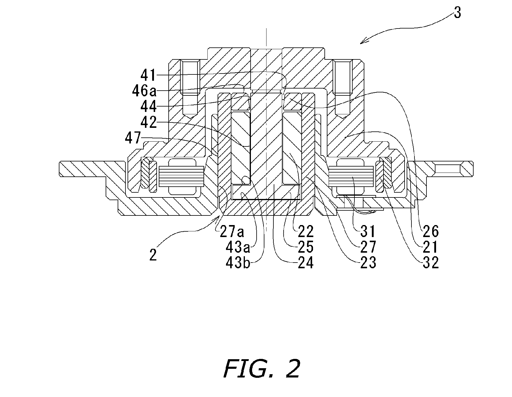
[0070] The spindle motor 3 is, as depicted in FIG. 2, furnished with: a rotor hub 21 having a carrying surface on which the recording disks 12 are carried; a toroidal rotor magnet 32 attached to the rotor hub 21; a bracket 27 that serves as the base co...

second embodiment

[0107] Spindle motor 103, as illustrated in FIG. 3, is utilized as an alternative to spindle motor 3 in the first embodiment. The recording disks 12 are carried on and spun by a rotor hub 121 of the spindle motor 103.

[0108] The spindle motor 103 is, in a like manner as in the first embodiment, made up of a fluid-dynamic-pressure bearing 102, a stator 32, and a rotor magnet 132. Likewise, in the spindle motor 103, a baseplate 127 that constitutes a part of the case 11 for the recording-disk drive 1 serves as the base component.

[0109] The fluid-dynamic-pressure bearing 102 includes: a columnar shaft 124 mounted in the rotational center portion of the rotor hub 121; a sleeve 122 having an inner circumferential surface that radially opposes the outer circumferential surface of the shaft 124; and the rotor hub 121, which has an underside surface that axially opposes the upper endface of the sleeve 122. The shaft 124 is composed of a hardened martensitic stainless steel, and the sleeve ...

third embodiment

[0123] The description now turns to FIG. 4, which is a diagram illustrating a spindle motor 203 and a fluid dynamic-pressure bearing 202 in yet another embodiment of the present invention.

[0124]FIG. 4 is of a fluid dynamic-pressure bearing 202 in which the shaft 224 is anchored into the bracket 227. This fluid dynamic-pressure bearing 202 is made up of: a sleeve 222 mounted in a rotor hub 221 of the spindle motor 203; the shaft 224, which is inserted into the sleeve 222; and a flange 225 that is mounted on the upper-end part of the shaft 224. The gap between the sleeve 222 and the shaft 224 is charged with and retains lubricating fluid 35. A radial dynamic-pressure bearing 242 is formed in between the outer circumferential surface of the shaft 224 and the inner circumferential surface of the sleeve 222. Furthermore, thrust dynamic-pressure bearings 243a and 243b are formed in between the top and bottom surfaces of the flange 225, and the sleeve 222 where it axially opposes the top / ...


PUM

PropertyMeasurementUnit
wetting angleaaaaaaaaaa
lengthaaaaaaaaaa

Abstract

In spindle motors journaled on fluid-dynamic-pressure bearings, especially in such spindle motors employed in recording-disk drives in implementations that subject the drives to vibration and shock, sealing performance of a capillary seal formed between motor rotor-side and stator-side bearing surfaces, cohesiveness of oil-repellant on rotor-side/stator-side dry-area surfaces adjoining the capillary seal section, and motor inter-component adhesive strength are improved. The capillary-seal-constituting rotor-side/stator-side surface(s) are exposed to a plasma or to ultraviolet rays under predetermined conditions to improve the wettability of the surface(s) for the bearing fluid. The dry-area surface(s) are similarly irradiated so as to improve their wettability for the oil-repellant. Adhesively bonded component surfaces are likewise irradiated so as to improve their wettability for the adhesive, enhancing adhesive strength. Exposed surfaces may be constituted of a synthetic resin to enhance their wettability further, or may be made of metal, to yield a cleaning efficacy from the plasma/UV exposure.

Description

BACKGROUND OF THE INVENTION [0001] 1. Technical Field [0002] The present invention relates to fluid-dynamic-pressure bearing manufacturing methods, to spindle motor manufacturing methods, and to spindle motors and recording-disk drives. [0003] 2. Description of the Related Art [0004] In recent years, the amount of information that is recorded per unit area on discoid recording media in hard-disk and like recording-disk drives has been increasing, and the information density has been on the rise. The increasing recording density has led to calls for stably supporting the discoid recording media under high-speed rotation. [0005] Recording-disk drives, meanwhile, are finding applications other than in stationary computers, such as desk-top and server machines, in which the drives have been traditionally employed, and are being used in vehicular devices, portable devices, and other mobile devices. Such mobile applications have led to rising demands for impact resistance and longevity-de...

Claims


Application Information

Patent Timeline
Patent Type & Authority Applications(United States)
IPC IPC(8): F16C32/06F16C33/10F16C33/74G11B19/20H02K1/00H02K5/167H02K7/08
CPCF16C33/103G11B19/2018H02K5/1675H02K5/1677H02K7/085H02K7/086F16C2370/12F16C2202/60F16C33/745F16C17/107Y10T29/49705Y10T29/49009Y10T29/49025Y10T29/49636Y10T29/49696Y10T29/49639
Inventor GOMYO, MASATOTAMAOKA, TAKEHITO
Owner NIPPON DENSAN CORP
Why Eureka
Try Eureka