Die cushion controlling apparatus and die cushion controlling method

Active Publication Date: 2005-12-15
KOMATSU LTD +1
View PDF5 Cites 41 Cited by
  • Summary
  • Abstract
  • Description
  • Claims
  • Application Information

AI Technical Summary

Benefits of technology

[0040] According to the present invention, since the pressure feedback control of the closed loop for feeding back the cushion pressure measured from the cushion pad itself is performed at a timing at which the pressure feedback control of the cushion pad is required, the cushion pressure of the c

Problems solved by technology

However, there is a drawback that the structure of a hydraulic apparatus is complicated, and severe maintenance and management is required.
An error of the control affects to throttling workability, and causes the work 4 to be broken or strained.
With respect to an accuracy of the operation of the cushion pad, the above-men

Method used


Image

  • Die cushion controlling apparatus and die cushion controlling method
  • Die cushion controlling apparatus and die cushion controlling method
  • Die cushion controlling apparatus and die cushion controlling method

Examples


first embodiment

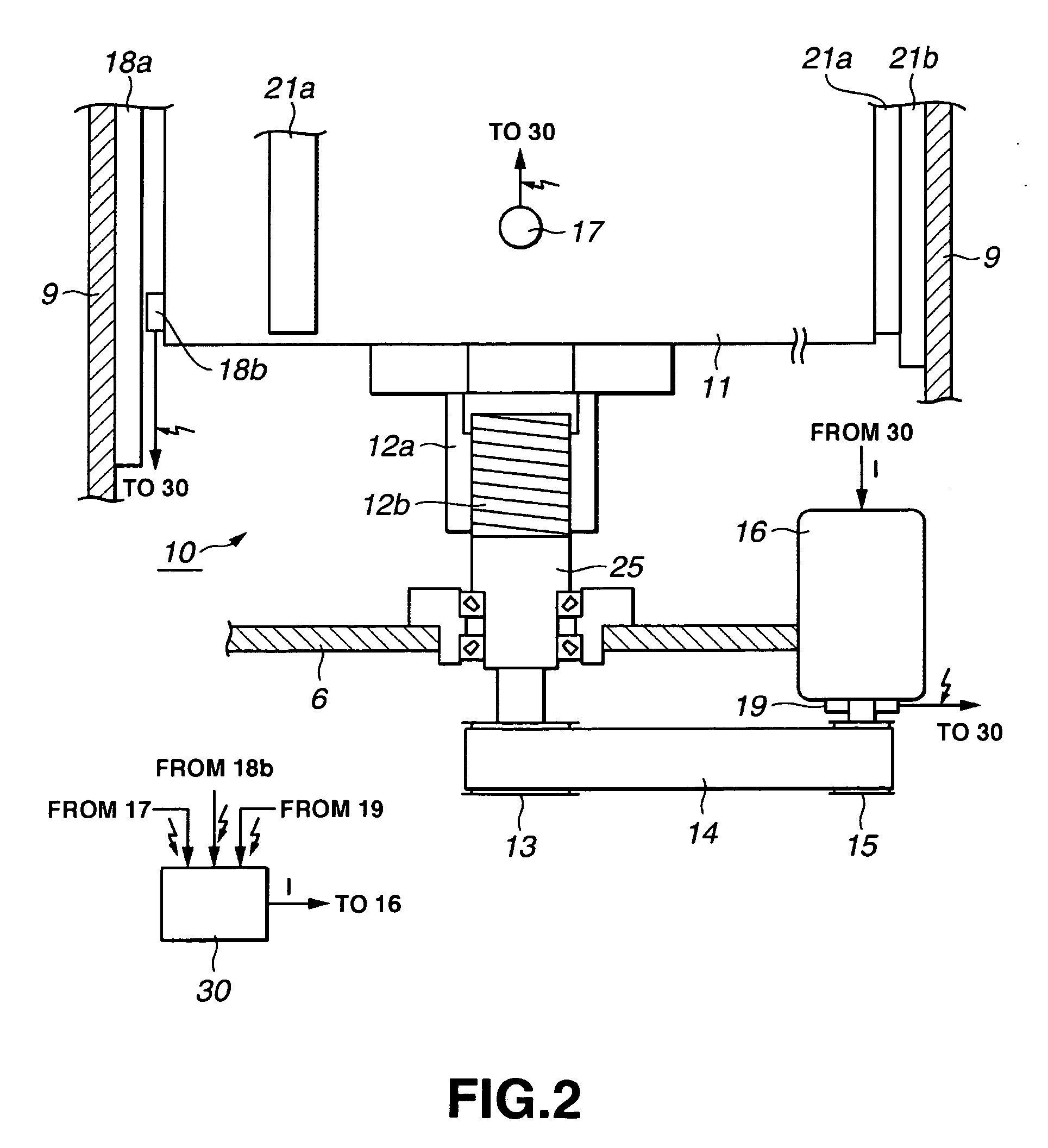
[0064]FIG. 2 is a schematic view of the die cushion according to the first embodiment. FIG. 3 is a top view of the die cushion according to the first embodiment.

[0065] In the die cushion 10, the cushion pad 11 is coupled to the rotary shaft of a servomotor 16 via a ball screw 12, a coupling member 25, a large pulley 13, a belt 14 and a small pulley 15. Powers of the cushion pad 11 and the servomotor 16 are transmissible to each other. A nut portion 12a of the ball screw 12 is coupled to a lower portion of the cushion pad 11. A threaded portion 12b of the ball screw 12 is engaged with the nut portion 12a. A lower part of the threaded portion 12b is connected to the coupling member 25. The coupling member 25 is supported to the beam 6 by a bearing, etc. and its lower part is coupled to the large pulley 13. The small pulley 15 is connected to the rotary shaft of the servomotor 16. The belt 14 is wound on the large pulley 13 and the small pulley 15, and the powers of the large pulley 1...

second embodiment

[0089]FIG. 6 is a schematic view of a die cushion according to the second embodiment. Concerning the die cushion 50 shown in FIG. 6, only different portion from the die cushion 10 shown in FIG. 2 will be described.

[0090] In the die cushion 50, the cushion pad 11 is coupled to a rotary shaft of the servomotor 16 via a ball screw 52, a coupling member 55, a large pulley 13, a belt 14 and a small pulley 15. Between the cushion pad 11 and the servomotor 16, powers are transmissible to each other. The threaded portion 52b of the ball screw 52 is coupled to the lower portion of the cushion pad 11. The threaded portion 52b of the ball screw 52 is engaged with a nut portion 52a. A lower part of the nut portion 52a is connected to the coupling member 55. The coupling member 55 is supported by a bearing, etc. to the beam 6, and its lower portion is coupled to the large pulley 13. The small pulley 15 is connected to the rotary shaft of the servomotor 16. A belt 14 is wound around the large pu...

third embodiment

[0094]FIG. 7 is a schematic view of a die cushion according to a third embodiment. FIG. 8 is a top view of the die cushion according to the third embodiment. Concerning the die cushion 60 shown in FIG. 7 and FIG. 8, only a portion different from the die cushion 10 shown in FIG. 2 will be described.

[0095] A linear servomotor 61 is provided between each side face of the cushion pad 11 and each inner wall surface of the bed 9 opposed to the side face of the cushion pad 11. The linear servomotor 61 includes a pair of a coil portion 61a and a magnet portion 61b. The coil portion 61a is provided on each side face of the cushion pad 11, and the magnet portion 61b is provided on the inner wall surface of the bed 9. Contrarily, the magnet portion 61b may be provided on each side face of the cushion pad 11, and the coil portion 61a may be provided on the inner wall surface of the bed 9. Incidentally, in FIG. 7, the linear servomotor 61 is shown only on the right side face of the cushion pad ...


PUM

PropertyMeasurementUnit
Pressureaaaaaaaaaa
Strain pointaaaaaaaaaa

Abstract

A die cushion controlling apparatus for controlling an operation of a cushion pad, which comprises a pad drive mechanism for driving to raise or lower the cushion pad while applying an upward energizing force, a load measuring unit for measuring a load generated in the cushion pad, a time detecting unit for detecting a generating time and a vanishing time of the load, and a control unit for controlling the pad drive mechanism so that a load measured value measured by the load measuring unit follows a preset load pattern during a period from when the time detecting unit detects the generating time of the load until when the time detecting unit detects the vanishing time of the load.

Description

BACKGROUND OF THE INVENTION [0001] 1. Field of the Invention [0002] The present invention relates to a die cushion controlling apparatus and a die cushion controlling method which controls an operation of a cushion pad synchronously with an operation of a slide of a press machine. [0003] 2. Description of the Related Art [0004] In a press machine, a die cushion apparatus (hereinafter merely referred to as a “die cushion”) is provided for controlling folds in a throttling work. A conventional die cushion generates a cushion pressure while driving to raise or lower a cushion pad by using a hydraulic pressure or an air pressure. In order to raising throttling workability of the press machine and prevent a work from being broken or strained, it is necessary to control the cushion pressure of the die cushion in high accuracy, and particularly, it is necessary to control the cushion pressure at the time of lowering operation of the cushion pad in high accuracy. [0005] The die cushion usin...

Claims


Application Information

Patent Timeline
IPC IPC(8): B21D24/10B26D1/00
CPCB21D24/10Y10T83/04
Inventor SHIROZA, KAZUHIKOTAKAYAMA, YUKIYOSHIHONMA, HIROAKISEKI, SEIJI
Owner KOMATSU LTD
Why Eureka
Try Eureka