Back sack with heat dissipation effect

US20050274766A1Inactive Publication Date: 2005-12-15TAIWAN PAIHO LTD

Image

  • Back sack with heat dissipation effect
  • Back sack with heat dissipation effect
  • Back sack with heat dissipation effect

Examples


Embodiment Construction

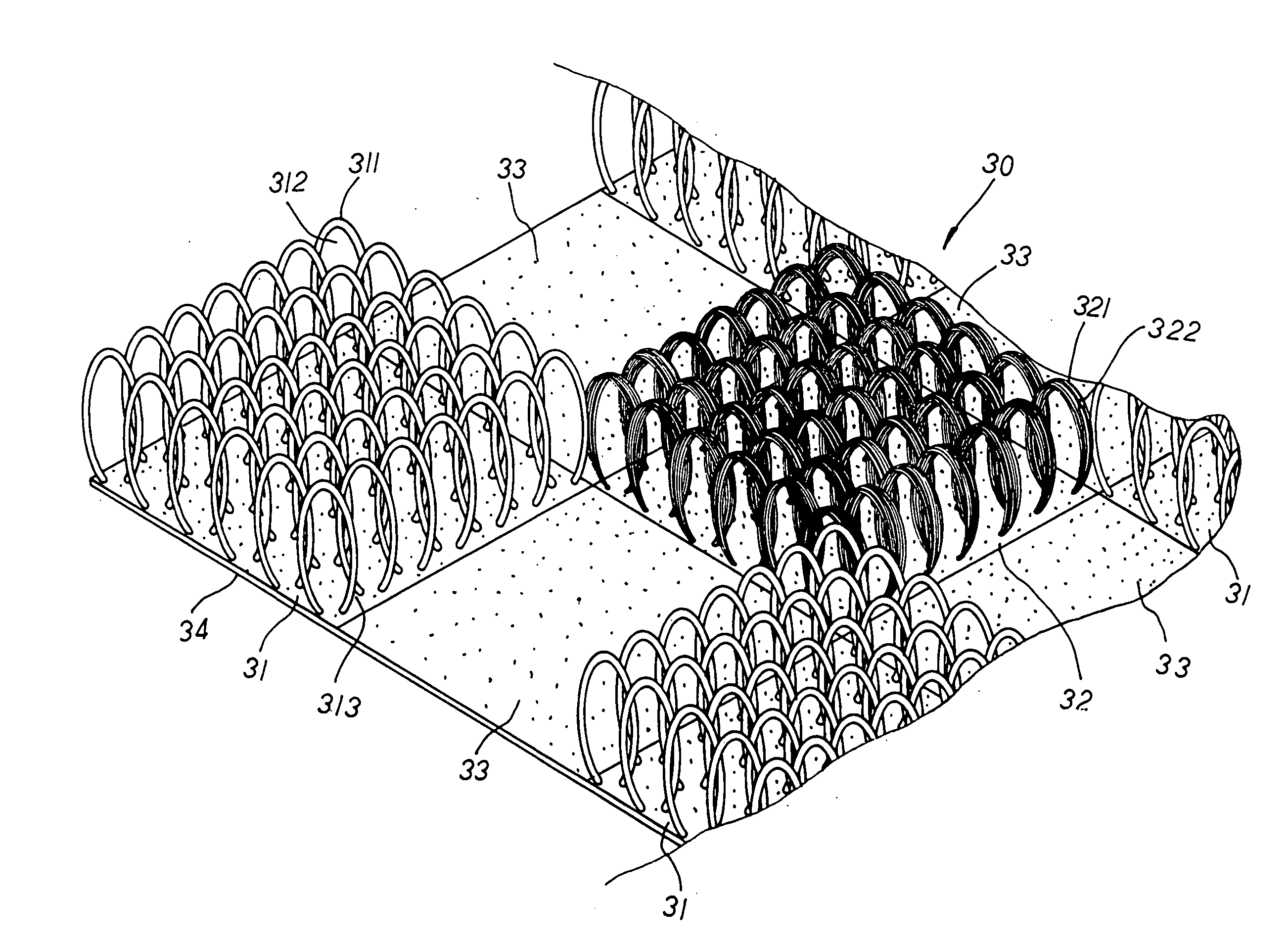
[0016] Please refer to FIGS. 3 to 8 inclusive. The present invention is related to a back sack with a heat dissipation effect, including a back pad 30 that, having bamboo charcoal contained therein, is integrally woven to form a plurality of resilient areas 31, heat-dissipation areas 32, and buffer areas 33 defining the top surface thereon. The resilient areas 31, heat-dissipation areas 32 and buffer areas 33 thereof can be made in any shapes such as rectangles or triangles as shown in FIG. 4, or oblique stripes as shown in FIG. 5, and are alternatively interrelated with respect to one another in regular or irregular arrangement thereof. The resilient areas 31 and the heat-dissipation areas 32 are respectively provided with a plurality of support hoops 311 and fleece rings 321 of a preset height densely and neatly arranged at the surface thereon. The support hoops 311 are stood upright in ring shapes with vents 312 defined therein and dividing passages 313 formed at the adjacent sid...


PUM


Abstract

A back sack with a heat dissipation effect includes a sack pad mounted to a back abutment facet of a back sack thereon wherein the back pad is integrally made with a plurality of resilient areas, heat-dissipation areas, and buffer areas defining the top surface thereon, and the resilient areas and the heat-dissipation areas thereof are respectively provided with a plurality of support hoops and fleece rings of a preset height densely and neatly arranged at the surface thereon. The support hoops of the resilient areas are stood upright with vents defined therein and dividing passages formed at the adjacent sides thereof, and a coupling facet is disposed at the bottom side of the sack pad thereof. Thus, when a human back is abutted against the resilient areas of the sack pad, the support hoops with a better ventilating capability can flexibly sustain the back thereof, reducing the density of contact areas between the back and the back abutment facet of the back sack to cut down the friction there-between as well as stimulating blood circulation to provide a better massage effect. And, via the fleece rings made up of multi-yarn fabrics with absorptive capacity and tiny pores, the heat-dissipation areas thereof can serve to absorb moisture, transpire perspiration, and dissipate heat, etc., effectively avoiding the uncomfortable feeling of sticky stuffiness generated at the back thereof to maintain the hygiene of the back sack thereof.

Description

BACKGROUND OF THE INVENTION [0001] The present invention is related to a back sack with a heat dissipation effect, including a sack pad mounted to a back abutment facet of a back sack thereon wherein the back pad is integrally made with a plurality of resilient areas, heat-dissipation areas, and buffer areas defining the upper surface thereon, and the resilient areas and the heat-dissipation areas thereof are respectively provided with a plurality of support hoops and fleece rings of a preset height densely and neatly arranged at the surface thereon. The support hoops of the resilient areas are stood upright with vents defined therein and dividing passages formed at the adjacent sides thereof; whereby, the sack pad is equipped with a better ventilating capability that can reduce the density of contact areas between a human back and the sack pad thereof so as to cut down the friction there-between. And, via the fleece rings made up of multi-yarn fabrics with absorptive capacity and t...

Claims


Application Information

Patent Timeline
15 Dec 2005
Publication
US20050274766A1
IPC
A45C3/00; H01L23/34; A45F3/04; A45F3/12
CPC
A45F3/04; A45F3/12; A45F2003/122; A45F2003/125
Inventors
CHENG, SEN-MEI