Real time high speed high resolution hyper-spectral imaging

a hyper-spectral imaging and high-speed technology, applied in the field ofspectral imaging, can solve the problems of not being able to study using regular hyper-spectral imaging techniques, unable to achieve the prior art teachings do not disclose a method or system for enabling high-speed grabbing and generating hyper-spectral, etc., to achieve high resolution, high resolution, and high resolution nanometer accuracy

Active Publication Date: 2005-12-15
GREENVISION SYST
View PDF23 Cites 48 Cited by
  • Summary
  • Abstract
  • Description
  • Claims
  • Application Information

AI Technical Summary

Benefits of technology

[0014] The present invention relates to a method and system for real time high speed high resolution hyper-spectral imaging. The present invention is based on using piezoelectric technology with closed loop control and analysis algorithms, for enabling real time high speed high resolution nanometer accuracy move

Problems solved by technology

‘High speed’ hyper-spectral imaging system is required for different types of repeatable and non-repeatable chemical and physical processes taking place during the sub-100 millisecond time scale and cannot, therefore, be studied using regular hyper-spectral imaging techniques.
However, none of these prior art teachings disclose a method or system for enabling high speed grabbing and generating hyper-spectral (cube) images, self spatial and spectral calibration capabilities and procedures, and rapid tunable fast scanning rate of, for example, less than 50 millisecond for an entire spectral (cube) image, as required by more sophisticated applications of hyper-spectral imaging.
Currently available hyper-spectral imaging techniques are significantly limited by having insufficiently high speeds of generating and processing spectral (cube) images, and are limi

Method used


Image

  • Real time high speed high resolution hyper-spectral imaging
  • Real time high speed high resolution hyper-spectral imaging
  • Real time high speed high resolution hyper-spectral imaging

Examples


Embodiment Construction

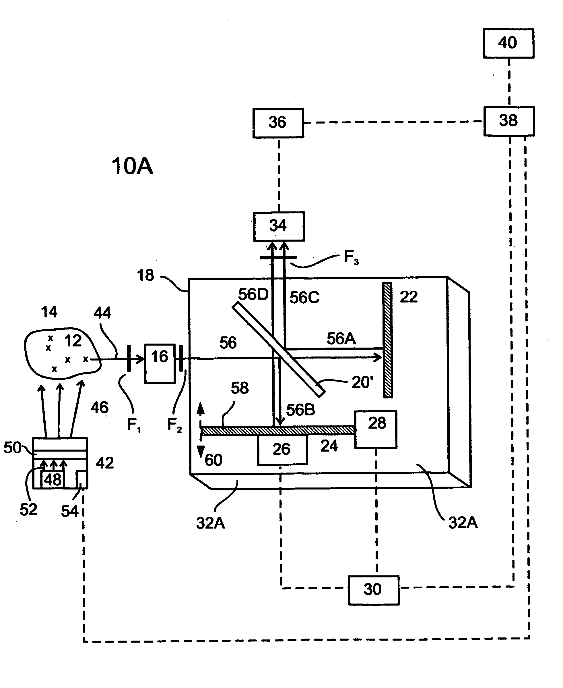
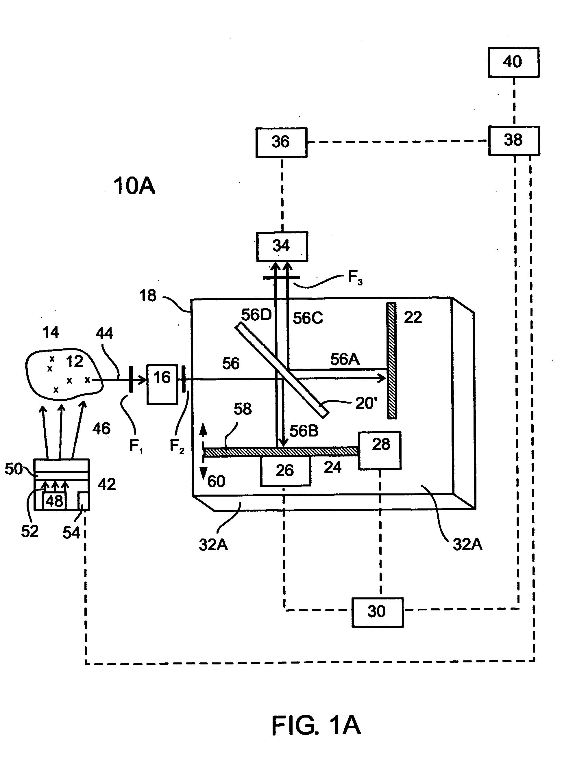
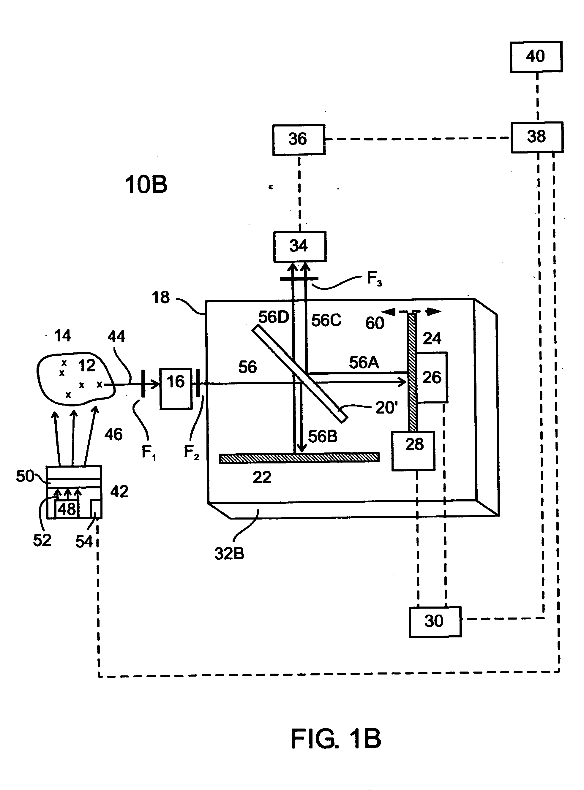
[0045] The present invention relates to a method and system for real time high speed high resolution hyper-spectral imaging. The present invention is based on using piezoelectric technology with closed loop control and analysis algorithms, for enabling real time high speed high resolution nanometer accuracy movement of a movable mirror in an optical interferometer, along with using a specially designed and constructed optical interferometer mount as part of the optical interferometer, for achieving high thermo-mechanical stability of mounted optical interferometer components during the real time hyper-spectral imaging.

[0046] The present invention features several aspects of novelty and inventiveness which are based on integration of a specially designed, constructed, and operative, optical interferometer in the hyper-spectral imaging system. The optical interferometer features real time high speed high resolution nanometer accuracy displacement or movement of the movable mirror, en...


PUM


Abstract

Real time high speed high resolution hyper-spectral imaging. (a) electromagnetic radiation collimating element (16), collimating electromagnetic radiation (44) emitted by objects (12) in a scene or a sample (14); (b) optical interferometer (18), receiving and dividing collimated object emission beam, generating interference images, and piezoelectrically determining and changing magnitude of optical path difference of divided collimated object emission beam; optical interferometer (18) includes: beam splitter (20′), fixed mirror (22), movable mirror (24), piezoelectric motor (26), displacing movable mirror (24) along axis (60), distance change feedback sensor (28), sensing and measuring change in distance of movable mirror (24) along axis (60), piezoelectric motor controller (30), actuating and controlling piezoelectric motor (26); and thermo-mechanically stable optical interferometer mount (32A); (c) camera optics (34), focusing interference images of each optical path difference; (d) detector (36), recording interference images; processing unit (38), and (f) display (40).

Description

FIELD AND BACKGROUND OF THE INVENTION [0001] The present invention relates to spectral imaging and, more particularly, to a method and system for real time high speed high resolution hyper-spectral imaging. The present invention is based on using piezoelectric technology with closed loop control and analysis algorithms, for enabling real time high speed high resolution nanometer accuracy movement of a movable mirror in an optical interferometer, along with using a specially designed and constructed optical interferometer mount as part of the optical interferometer, for achieving high thermo-mechanical stability of mounted optical interferometer components during the real time hyper-spectral imaging. Implementation of the present invention results in high speed collecting of high resolution interferogram images used for synthesizing and analyzing high resolution highly reproducible three-dimensional hyper-spectral (cube) images. [0002] In the general technique of spectral imaging, in...

Claims


Application Information

Patent Timeline
IPC IPC(8): G01J3/28G01J3/453
CPCG01J3/02G01J3/0202G01J3/021G01J3/0237G01J3/4535G01J3/0291G01J3/2823G01J3/4532G01J3/0259
Inventor MOSHE, DANNY S
Owner GREENVISION SYST
Why Eureka
Try Eureka