Network relay system and control method thereof

Inactive Publication Date: 2005-12-15
HITACHI LTD
View PDF2 Cites 41 Cited by
  • Summary
  • Abstract
  • Description
  • Claims
  • Application Information

AI Technical Summary

Benefits of technology

[0014] The object of the present invention is thus to eliminate the drawbacks of the prior art discussed above and to provide a technique that effectively prevents the double master situation and restrains the occurrence of a loop in a network.
[0018] The network relay device of the invention changes the working state from the backup state to the master state after confirmation that the working state of the pairing specific network device is in the backup state. This arrangement effectively prevents both the network relay device and the pairing specific network device from being simultaneously set in the master state (double master situation) and thereby restrains the occurrence of a loop in the network.
[0021] In the event of failed transmission of the control frame signal from the specific network device that is in some busy status, the control module in the network relay device of the invention changes the working state to the second intermediate state on the condition that the control frame signal has not been received for the preset time period. Namely the network relay device of the invention does not immediately change its working state to the master state. When the specific network device resumes transmission of the control frame signal in response to cancellation of the busy status, the control module in the network relay device of the invention resumes reception of the control frame signal and selects either the master mode or the backup mode. The working state is changed to the first intermediate state in response to selection of the master mode, while being changed to the backup state in response to selection of the backup mode. This arrangement effectively prevents the double master situation.
[0023] In the event of failed transmission of the control frame signal due to the occurrence of some trouble or failure in the specific network device, the network relay device of the invention changes the working state to the second intermediate state after elapse of the preset time period. In the case of the occurrence of some trouble or failure, it is expected that failed reception of the control frame signal from the specific network device continues. The working state is directly changed to the master state, in response to input of externally given transition instruction to the master state. The network relay device of the invention thus takes over the master mode in place of the specific network device. This attains a changeover from the active system to the standby system in the network and thereby ensures the redundancy of the network.
[0025] In the network including a large number of virtual LANs, it is preferable to carry out the control and management discussed above with regard to each group of a single or multiple virtual LANs. This arrangement effectively prevents the double master situation and restrains the occurrence of a loop in each virtual LAN.

Problems solved by technology

The occurrence of the loop in the network may lead to a significant problem.
This applies significant loading to the packet transfer of the L2 switch and affects other networks to occupy the available bandwidth.
This leads to a switchover of the entire network from the active system to the standby system.
The control module in the busy status may, however, fail to send the control frame signal to the backup L2 switch.
This undesirably causes a loop in the network.

Method used


Image

  • Network relay system and control method thereof
  • Network relay system and control method thereof
  • Network relay system and control method thereof

Examples


Embodiment Construction

[0035] One mode of carrying out the invention is discussed below in the following sequence: [0036] A. Configuration of Embodiment [0037] B. Connection [0038] C. Operations of Embodiment [0039] D. Modifications

A. Configuration of Embodiment

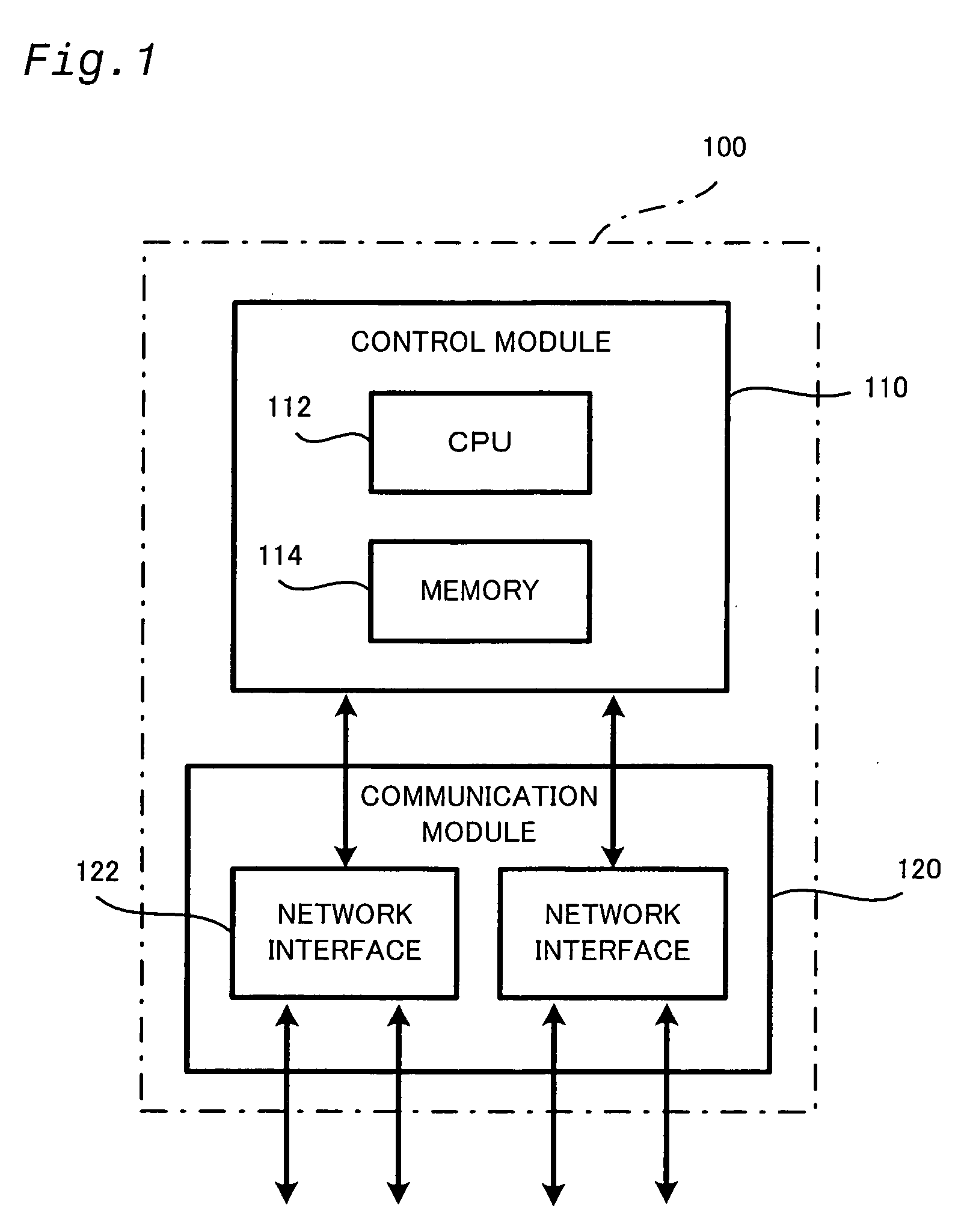
[0040]FIG. 1 is a block diagram showing the configuration of an L2 switch 100 in one embodiment of the invention. As shown in FIG. 1, the L2 switch 100 of the embodiment mainly includes a control module 110 and a communication module 120. The control module 110 has a CPU 112 and a memory 114. The CPU 112 executes programs stored in the memory 114 to manage the whole system, process control packets, and send and receive control frame signals. The communication module 120 includes network interfaces 122 and relays packets on a layer 2 (data link layer) of the OSI reference model. The network interfaces 122 are respectively connected to physical lines (for example, twisted pair cables or optical fibers) of Ethernet (registered trademark) or another...


PUM


Abstract

The network relay device of the invention makes a pair with at least a specific network device to relay data in a network. The network relay device includes: a control module that sends and receives a control frame signal to and from the specific network device, selects either of a master mode and a backup mode based on at least the control frame signal sent from the specific network device, and changes a working state according to a result of the selection; and a communication module that is under control of the control module to open a port and enable data transmission via a line linked to the port in the case of setting a master state to the working state, and to block off the port and disconnect the line linked to the port in the case of setting a backup state or another non-master state to the working state. The control module changes the working state from the backup state to a first intermediate state in response to selection of the master mode, determines whether the specific network device is in the backup state, based on the control frame signal sent from the specific network device, and changes the working state from the first intermediate state to the master state after confirmation that the specific network is in the backup state.

Description

BACKGROUND OF THE INVENTION [0001] 1. Field of the Invention [0002] The present invention relates to a network relay device that relays data in a network. [0003] 2. Description of the Related Art [0004] The network generally adopts the redundant structure, in order to prevent the shutdown of the entire network due to the occurrence of some trouble or failure in a line or a device included in the network. [0005] A layer 2 (data link layer) and a layer 3 (network layer) in the OSI reference model have different network characteristics. In the case of an internet protocol (IP) as a typical example of the layer 3, simple connection of two devices by a physical line does not establish intercommunication between the connected devices unless IP addresses are set in the respective devices. In the case of Ethernet (registered trademark) as a typical example of the layer 2, on the other hand, simple connection of two devices by a physical line establishes intercommunication between the connec...

Claims


Application Information

Patent Timeline
IPC IPC(8): H04L12/26H04L12/46
CPCH04L49/55H04L49/1523
Inventor KITANI, MAKOTOWATANUKI, TATSUYAYAMATE, KEIICHIROKIMOTO, ATSUSHI
Owner HITACHI LTD
Why Eureka
Try Eureka