
Punch assembly with spinning head

a technology of punching head and spinning head, which is applied in the field of punching and equipment, can solve the problems of not being able to provide excellent service for the entire range of common web materials, not serving well for cutting through plastic film cleanly,

Inactive Publication Date: 2005-12-15
POTTORFF EARL T
View PDF22 Cites 37 Cited by
  • Summary
  • Abstract
  • Description
  • Claims
  • Application Information

AI Technical Summary

Benefits of technology

[0006] Accordingly, it is an object of this invention to provide a hole cutter or hole punch which can be used for punching holes and perforations in webs of a wide variety of types and thicknesses of material, and which avoids the drawbacks of the prior art.
[0008] It is another object of the invention to provide a hole punch assembly which can be easily changed over to create holes of various diameters.
[0009] It is a further object to provide a punch and hold-down clamp arrangement that is of simple design for long life and low maintenance costs.

Problems solved by technology

However, the hollow spindle is invariably provided without cutting teeth at its tip, and would not serve well for cutting through plastic film cleanly, without pulling or tearing it.
It has been desired to be able to use a plastic-head punch on films of various compositions and a wide variety of thicknesses, as well as on materials that may include some fiber content (e.g., paper or paper-filled materials), but existing punches have not provided excellent service for the entire range of common web materials.

Method used


Image

  • Punch assembly with spinning head
  • Punch assembly with spinning head
  • Punch assembly with spinning head

Examples


Embodiment Construction

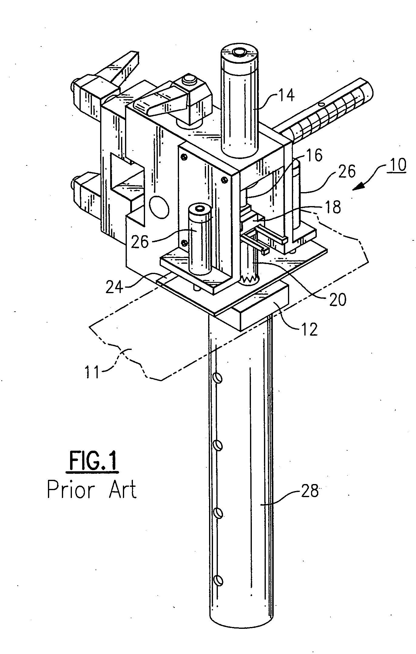
[0021] With reference to the Drawing, FIG. 1 illustrates a hole punch assembly 10 according to the state of the art, for punching holes into a web of plastic film 11. An apertured backing plate 12 supports the film 11, and has a round opening with which the hole punch blade or cutter head is aligned. A reciprocating actuator 14 has a shaft 16 that moves up and down with respect to the backing plate, and a vertical channel (not shown here) is situated distally of the shaft 16 for maintaining alignment of the assembly. Here, a punch and quick adapter assembly 18, e.g., as described in U.S. Pat. No. 6,148,700, can be fitted onto a threaded end of the shaft, and a punch head unit 20 fits into this adapter. The unit 20 has a circular hole punch that aligns with the opening in the apertured backing plate 12. As further shown in FIG. 1, a clamping plate 24 is situated between the hole punch unit 20 and the apertured backing plate 12. Here, the clamping plate has an opening or openings that...


PUM

PropertyMeasurementUnit
flexibleaaaaaaaaaa
diameteraaaaaaaaaa
sizesaaaaaaaaaa

Abstract

A spinning-head punch assembly has a crown-shaped cutting head that rotates at a high rate of speed, creating high quality holes in webs of plastic film or other materials. A rotary drive such as an electric motor is mounted on a reciprocating carriage above an apertured backing plate, and a pneumatic cylinder is actuated to thrust the cutting head toward the web. A spring biased clamp holds the web firmly around the die hole. In the first part of the punch cycle, the clamp closes down onto the web, and then the spinning cutting head contacts the web. The teeth on the web pierce the material so the punch cuts a clean hole, and does not pull or tear the material. Then on the second part of the punch cycle, the pneumatic cylinder lifts the cutting head away from the web material, and as the carriage reaches the top of its stroke the clamp releases the web so that it can advance to the next hole location.

Description

BACKGROUND OF THE INVENTION [0001] The present invention relates to punches and apparatus for perforating film material such as polyethylene film or other films made of plastic resin. The invention is more particularly directed to apparatus for making holes and perforations in a web or sheet of a plastic film. The invention is specifically directed to a punch assembly that can hold the web down while the holes are being formed, and which can be operated at a high speed without tearing or damaging the web material. [0002] Blades, punches, and cutters for forming holes and slits in plastic film material are described in prior U.S. Pat. Nos. 4,748,920 and 4,723,466 of Earl T. Pottorff. There, a self-sharpening hole punch formed of a low-friction, semi-rigid material, such as a polymer or a similar plastic resin. The hole punch has a thread at its upper end for screw-mounting onto reciprocating apparatus, which may be actuated by a pneumatic cylinder. These hole punches may have a gener...

Claims


Application Information

Patent Timeline
Patent Type & Authority Applications(United States)
IPC IPC(8): B23B39/00B26F1/16
CPCY10T408/56245B26F1/16
Inventor POTTORFF, EARL T.
Owner POTTORFF EARL T
Features
  • Generate Ideas
  • Intellectual Property
  • Life Sciences
  • Materials
  • Tech Scout
  • Unparalleled Data Quality
  • Higher Quality Content
  • 60% Fewer Hallucinations
Learn More