
Broad ion fragmentation coverage in mass spectrometry by varying the collision energy

Inactive Publication Date: 2005-12-15
MDS CO LTD +2
View PDF15 Cites 34 Cited by
  • Summary
  • Abstract
  • Description
  • Claims
  • Application Information

AI Technical Summary

Benefits of technology

[0011] Alternatively, the collision energy may be controlled by varying the background gas pressure in the collision cell over a period of time, whilst keeping the voltage potential or upstream pressure gradient constant. This technique is not presently preferred because of the practical difficulties in varying pressure over very short time frames.
[0012] According to another aspect of the invention, a quadrupole mass spectrometer is provided which includes at least first and second quadrupole rod sets arranged in linear formation and a mass analyzer operatively coupled to the second rod set. The first quadrupole rod set is configured for isolating selected ions. The second quadrupole rod set is enclosed within a collision chamber having a background gas pressure significantly higher than the first rod set. Means are provided for varying the voltage potential between the first rod set and second rod set (or chamber) so as to vary the injection energy applied to ions streaming into the collision chamber, to thereby vary the collision energy experienced by the ions. The mass analyzer may be a time-of-flight (TOF) device, a magnetic sector device, a quadruple mass filter, linear ion trap, or other means for obtaining a mass spectrum.
[0013] According to yet another aspect of the invention, a quadrupole mass spectrometer is provided which includes first, second and third quadrupole rod sets arranged in linear formation. The first quadrupole rod set is configured for isolating selected ions. The second quadrupole rod set is enclosed within a collision chamber having a background gas pressure significantly higher than the first and third rod sets. The third quadrupole rod set is configured as a linear ion trap. Means are provided for varying the voltage potential between the first and second rod sets (or chamber) so as to vary the injection energy applied to ions streaming into the collision chamber, to thereby vary the collision energy experienced by the ions.

Problems solved by technology

This technique is not presently preferred because of the practical difficulties in varying pressure over very short time frames.

Method used


Image

  • Broad ion fragmentation coverage in mass spectrometry by varying the collision energy
  • Broad ion fragmentation coverage in mass spectrometry by varying the collision energy
  • Broad ion fragmentation coverage in mass spectrometry by varying the collision energy

Examples


Embodiment Construction

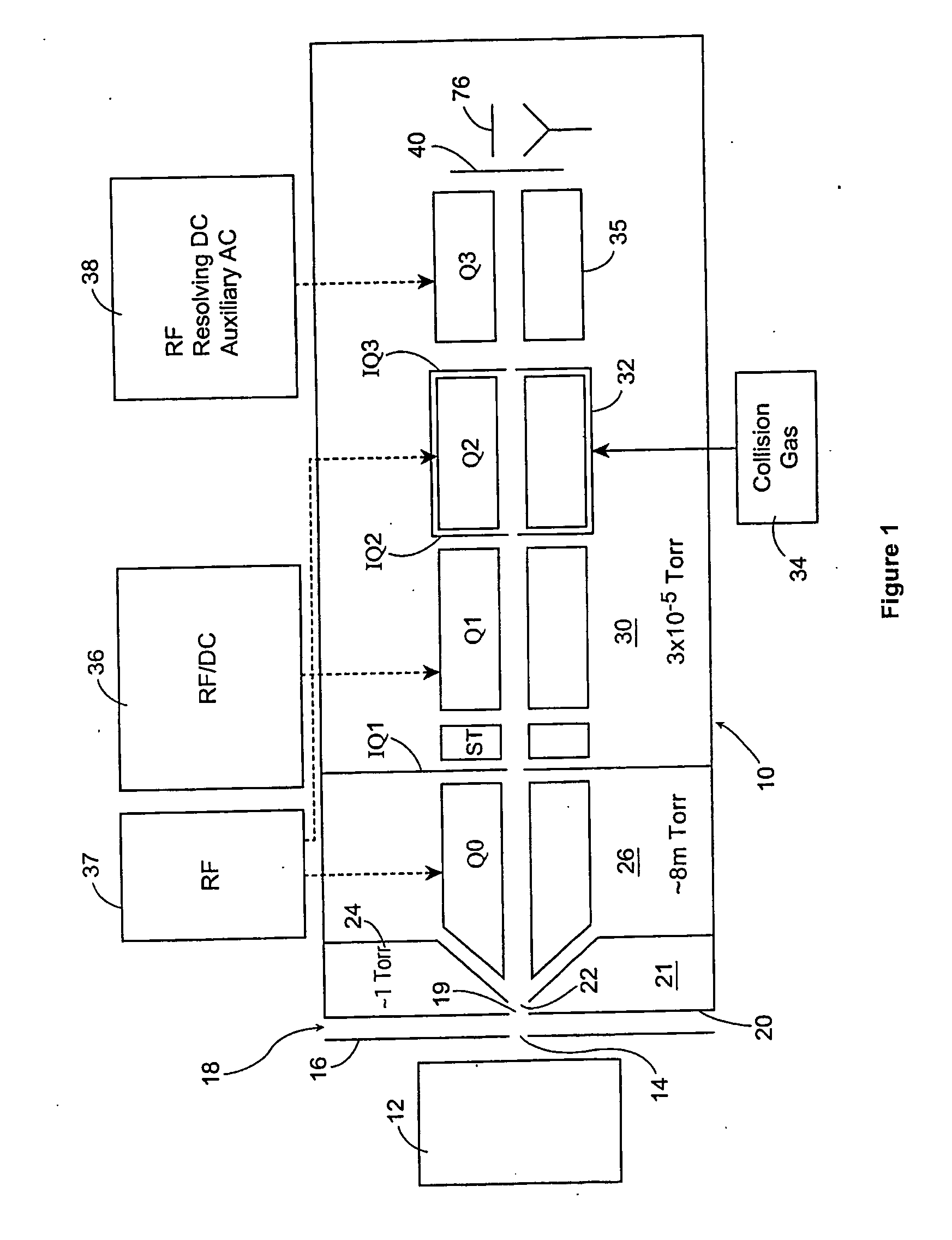
[0018]FIG. 1 illustrates a mass spectroscopy apparatus 10 in accordance with a first embodiment. In a known manner, the apparatus 10 includes an ion source 12, which may be an electrospray, an ion spray, a corona discharge device or any other known ion source. Ions from the ion source 12 are directed through an aperture 14 in an aperture plate 16. On the other side of the plate 16, there is a curtain gas chamber 18, which is supplied with curtain gas from a source (not shown). The curtain gas can be argon, nitrogen or other inert gas, such as described in U.S. Pat. No. 4,861,988, to Cornell Research Foundation Inc., which also discloses a suitable ion spray device. The contents of this patent are incorporated herein by reference.

[0019] The ions pass through an orifice 19 in an orifice plate 20 into a differentially pumped vacuum chamber 21. The ions then pass through aperture 22 in a skimmer plate 24 into a second differentially pumped chamber 26. Typically, the pressure in the dif...


PUM

PropertyMeasurementUnit
pressureaaaaaaaaaa
pressureaaaaaaaaaa
pressureaaaaaaaaaa

Abstract

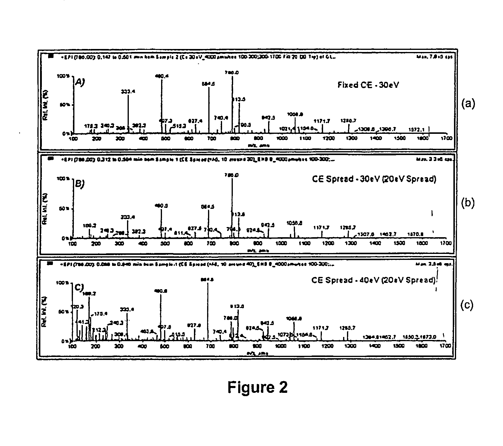
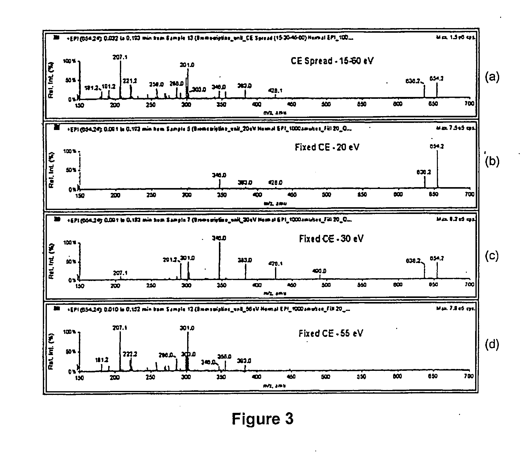
In the field of mass spectrometry, a method of obtaining a mass spectrum enriched with fragment ions while retaining the precursor ion. The technique includes varying the collision energy experienced by the precursor ion such that a range of fragmentations occur. Related methods are also disclosed for obtaining MS, MS2, MS3 and MSn spectra which are enriched with fragment ions.

Description

FIELD OF INVENTION [0001] The invention relates to mass spectrometers, and more particularly to a mass spectrometer capable of obtaining improved ion fragmentation spectra. BACKGROUND OF INVENTION [0002] Mass spectrometry techniques typically involve the detection of ions that have undergone physical change(s) in a mass spectrometer. Frequently, the physical change involves fragmenting a selected precursor ion and recording the mass spectrum of the resultant fragment ions. The information in the fragment ion mass spectrum is often a useful aid in elucidating the structure of the precursor ion. The general approach used to obtain a mass spectrometry / mass spectrometry (MS / MS or MS2) spectrum is to isolate a selected precursor ion with a suitable m / z analyzer, to subject the precursor ion to energetic collisions with a neutral gas in order to induce dissociation, and finally to mass analyze the fragment ions in order to generate a mass spectrum. [0003] Triple quadrupole mass spectromet...

Claims


Application Information

Patent Timeline
Patent Type & Authority Applications(United States)
IPC IPC(8): B01D59/44G01N27/62C07C209/00H01J49/00H01J49/04H01J49/26H01J49/42
CPCH01J49/063H01J49/005
Inventor BLOOMFIELD, NICLEBLANC, YVES
Owner MDS CO LTD
Learn More