Multiple detonation initiator for frequency multiplied pulsed detonation combustion

Active Publication Date: 2005-12-22
GENERAL ELECTRIC CO
View PDF5 Cites 30 Cited by
  • Summary
  • Abstract
  • Description
  • Claims
  • Application Information

AI Technical Summary

Benefits of technology

[0007] In an embodiment of the invention, a high frequency of detonation is achieved by using a plurality of detonation initiators with a main pulse detonation combustor, where the detonation initiators operate out-of-phase with each other. Each of the initiators operates at a lower frequency than the main pulse detonation combustor, but because they are operating out-of-phase with each other, the operational fre

Problems solved by technology

Because of the nature of the operation of pulse detonation combustors (i.e. a series of discrete detonations), there is a limit to the frequencies at which conventional simple tube pulse detonation combustors can operate.
One of the limitat

Method used


Image

  • Multiple detonation initiator for frequency multiplied pulsed detonation combustion
  • Multiple detonation initiator for frequency multiplied pulsed detonation combustion
  • Multiple detonation initiator for frequency multiplied pulsed detonation combustion

Examples


Embodiment Construction

[0014] The present invention will be explained in further detail by making reference to the accompanying drawings, which do not limit the scope of the invention in any way.

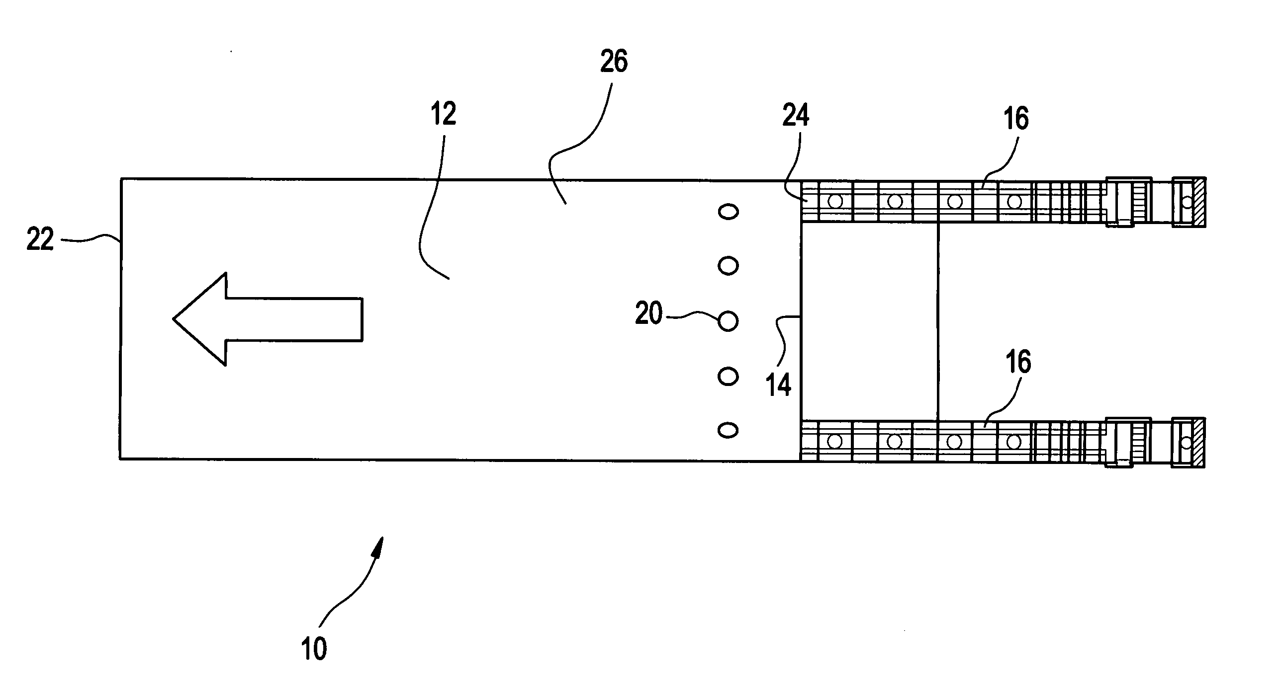
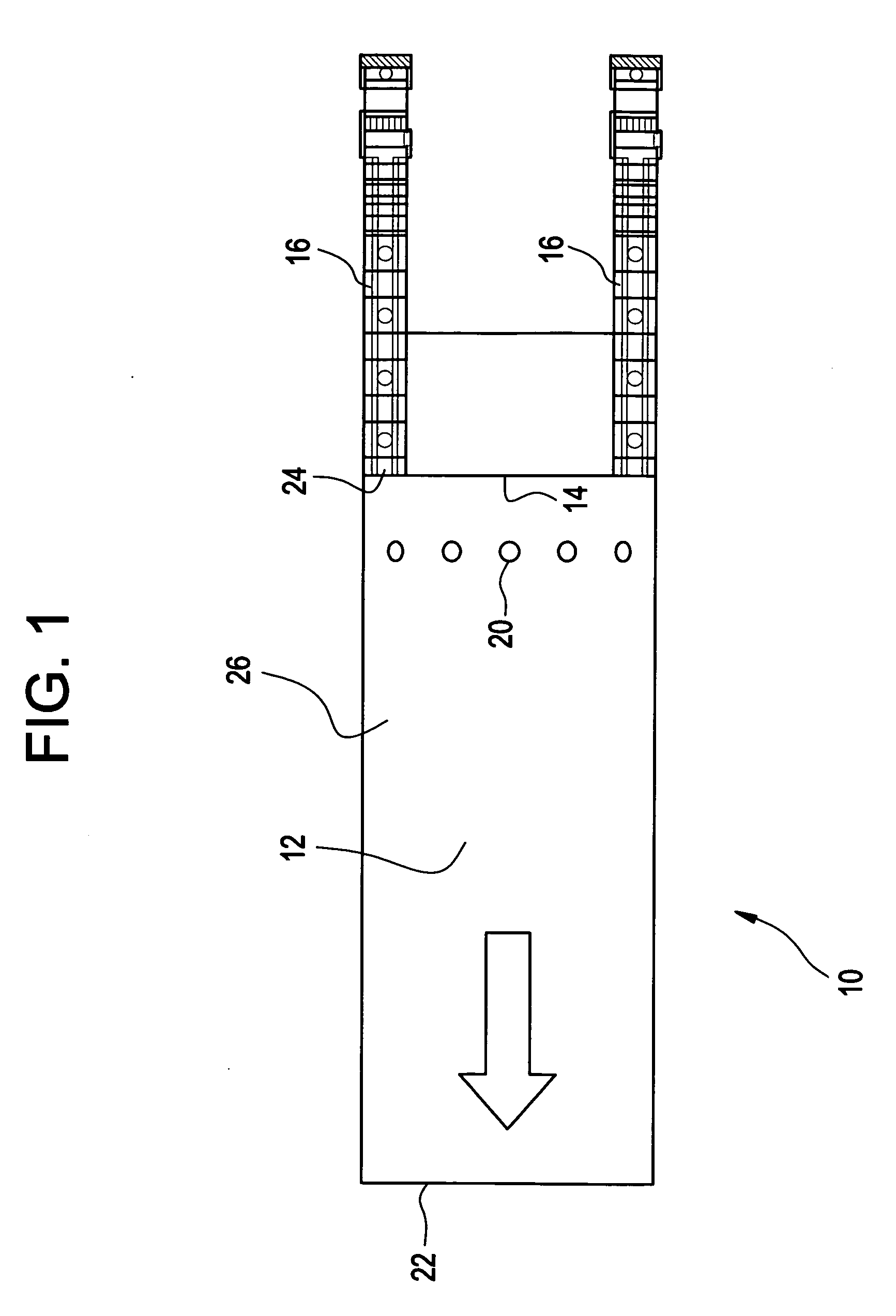
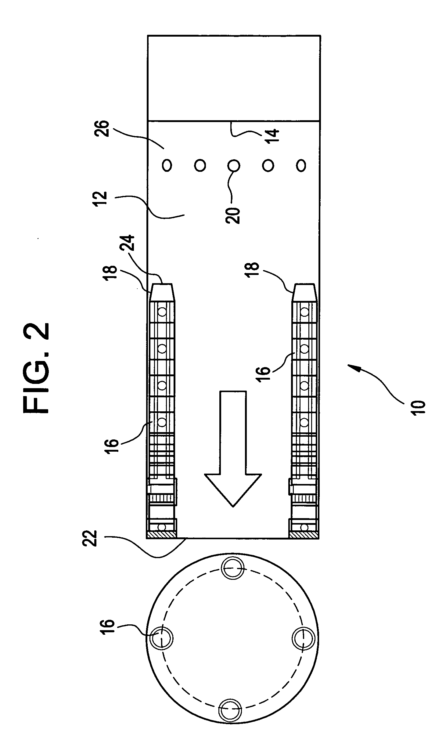
[0015]FIGS. 1-3 are diagrammatical representations of various embodiments of the pulse detonation combustor 10 of the present invention. The pulse detonation combustor 10 contains a main combustion chamber 12, a main combustor resonator surface 14, a plurality of detonation initiators 16, at least one inlet port 20 and a main combustor exit 22. FIG. 4 is a graphical timeline for the operation of an embodiment of the invention.

[0016] A detailed discussion of the operation and structure of the pulse detonation combustor 10 is set forth below.

[0017] During the operation of the pulse detonation combustor 10 a mixture of a gas, typically air, and a fuel, typically a hydrocarbon fuel, are placed into the main combustion chamber 12, which is cylindrical in shape. The fuel and gas enter the main combustion chamber 12 t...


PUM


Abstract

The present invention is a pulse detonation combustion system, having a plurality of detonation initiation devices coupled to a main combustion chamber, where each of the detonation initiation devices is operating out-of-phase with each other. Each of the detonation initiation devices assists in the initiation of a detonation in the main combustion chamber, out-of-phase from each other such that the operational frequency of the pulse detonation combustion system is related to the number of detonation initiation devices multiplied by the operational frequency of a single detonation initiation device.

Description

[0001] This invention was made with government support under Contract No. DABT63-00-C-0001 awarded by DARPA. The government may have certain rights to the invention.BACKGROUND OF THE INVENTION [0002] This invention relates to pulse detonation engines, and more particularly, to multiple detonation initiators for pulse detonation combustors. [0003] In recent years, efforts to address the need of a combination of combustion systems to obtain a wide range of flight speeds for aircraft have led to the development of pulse detonation combustors, which can be used on aircraft engines (as well as other applications). When used on aircraft engines, pulse detonation engines aid in increasing the available flight speed range of an aircraft engine while reducing the need for a combination of combustion systems. [0004] Pulse detonation combustors create high pressure and temperature detonation waves by combusting a mixture of gas (typically air) and a hydrocarbon fuel. The detonation waves exit ...

Claims


Application Information

Patent Timeline
IPC IPC(8): F02C5/00F02K7/02F23R7/00
CPCF02C5/00F23R7/00F02K7/02
Inventor DEAN, ANTHONY JOHNMCMANUS, KEITH ROBERTTANGIRALA, VENKAT ESWARLU
Owner GENERAL ELECTRIC CO
Why Eureka
Try Eureka